11
Extender Kit with Remote/Repeater Installation
3
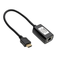
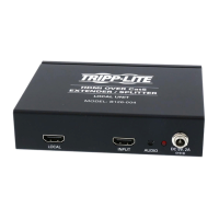
Optional for B126-1A1: Connect a local monitor to the LOCAL
HDMIportusingaTrippLiteP568-SeriesHDMICable.
4
Connect the external power supply to the local unit and plug it into a
Tripp Lite Surge Suppressor, PDU or UPS. The green LED illuminates
to indicate the unit is receiving power from the external power
supply.
5
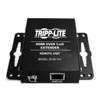
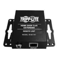
UsingCat5e/6cable,connecttheRJ45portonthelocalunittothe
RJ45INPUTportontheB126-110remote/repeaterunit.
6
Connect a monitor to the HDMI OUTPUT port on the remote/repeater
unitusingaTrippLiteP568-SeriesHDMICable.
7
Connect the external power supply to the remote/repeater unit and
plug it into a Tripp Lite Surge Suppressor, PDU or UPS. The green
powerLEDandthegreenRJ45LEDsilluminatetoindicatetheunit
is receiving power.
Upto4unitscanbedaisy-chained(3remote/repeatersand1receiver).
Toconnectadditionalremote/repeaterunits,proceedtostep8.Tonish
your installation with the B126-1A1 or B126-1A1-WP remote receiver
unit, proceed to step 12.
8
UsingCat5e/6cable,connecttheRJ45OUTPUTportontherst
remote/repeaterunittotheRJ45INPUTportonasecondremote/
repeater unit.
9
Connect a monitor to the HDMI OUTPUT port on the remote/repeater
unityoujustaddedusingaTrippLiteP568-SeriesHDMICable.
10
Connect the external power supply to the remote/repeater unit and
plug it into a Tripp Lite Surge Suppressor, PDU or UPS. The green
powerLEDandthegreenRJ45LEDsilluminatetoindicatetheunit
is receiving power.
201109206-93-3023-EN.indd 11 10/24/2011 10:01:21 AM
 Loading...