1306
Regulator/Rectifier
Internally the rectifier/regulator consists of three diodes, one between each input and
the positive terminal, and three Field Effect Transistors (FETs), one between each input
and the ground terminal.
As the voltage of the AC signal from the alternator rises, the voltage controller switches
the FETS to avoid over voltage on the output.
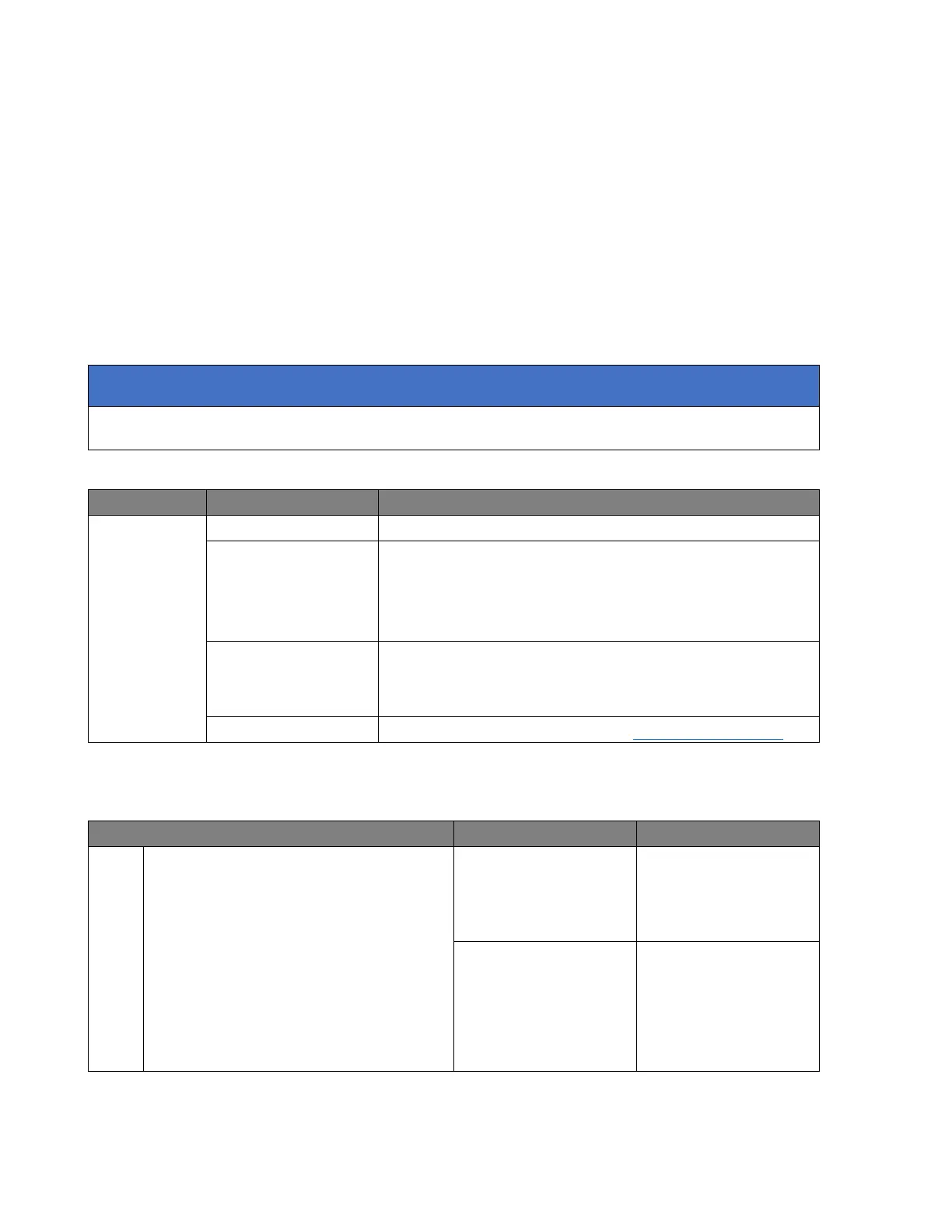
The diodes and FETs can be checked using a multimeter on DIODE setting. Disconnect
the two electrical connectors from the rectifier/regulator and check the readings as
indicated below.
This test does not check for voltage regulation.
Check the condition of the main 30A fuse:
Check the condition of the battery. Test the battery
using the BatteryMate 150-9. Refer to the
instructions supplied with the BatteryMate 150-9.
Ensure the battery is serviceable:
Disconnect the black and the grey connectors from
the rectifier/regulator and proceed to pinpoint test
1:
Test the alternator stator (see Alternator Stator).
Check FET forward bias:
Positive (+) probe to rectifier black
socket pin 1 to:
- Negative (-) probe to rectifier
grey socket pin 1
- Negative (-) probe to rectifier
grey socket pin 2
- Negative (-) probe to rectifier
grey socket pin 3
Open circuit or
short circuit
Replace the unit.
Proceed to test 4