36
Splices
Splices are probably the most common cause of wiring faults after connectors. Splices
are made where two or more wires come together and diverge in different directions,
usually to feed a different circuit.
To locate a splice, it is necessary to peel back the insulation and examine the splice for
its integrity. The most common fault is where one of the wires at the joint has come
adrift usually causing the circuit it feeds or grounds to become 'dead'.
Switches
To check a switch, set the multimeter to resistance/continuity and probe the two pins
that form a closed circuit when the switch is pushed. If the switch is working correctly,
the resistance should register or the meter will bleep.
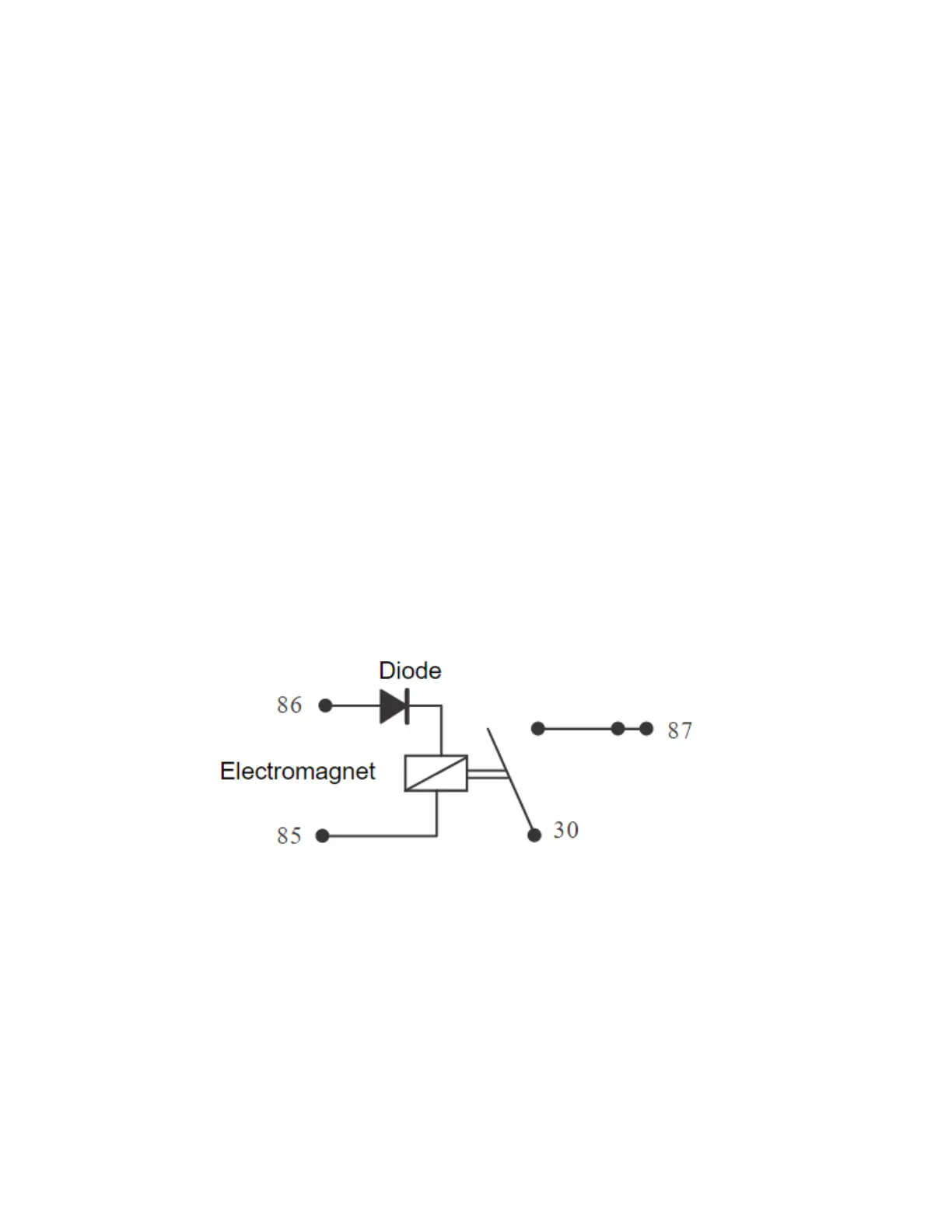
Relays
All relay cases have a circuit path engraved on them showing the circuit path across the
electromagnet and the switch. Before making any checks, first note the pin designations,
current paths, and whether or not there is a diode in either circuit path.
Make continuity checks across the electromagnet first, usually from pin 86 (positive) to
pin 85 (negative). If a diode appears in the circuit use the diode check on the multimeter
(Volts scale) in the direction of current flow. If there is no diode, use the resistance check
facility. An open circuit or unusually high resistance value indicates a faulty relay.
To check the switch side, apply a 12 Volt supply between pins 86 and 85. With the supply
connected, the relay should be heard to click and there should be continuity between
pins 30 and 87. An open circuit indicates a faulty relay.