CLUTCH
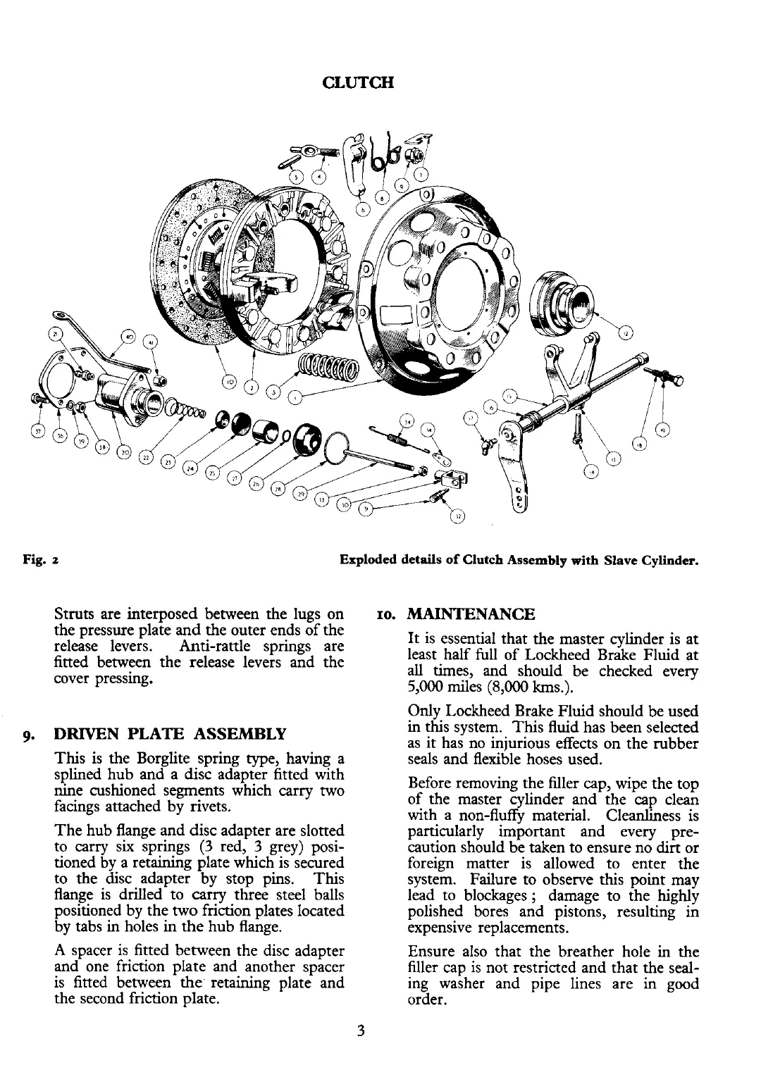
Fig.
z
Exploded details
of
Clutch Assembly with Slave Cylinder.
Struts are interposed between the lugs on
the pressure plate and the outer ends of the
release levers. Anti-rattle springs are
fitted between the release levers
and the
cover pressing.
9.
DRIVEN
PLATE ASSElMBLY
This is the Borglite spring type, having a
splined hub and a disc adapter fitted with
nine cushioned segments which carry two
facings attached by rivets.
The hub flange and disc adapter are slotted
to carry six springs
(3
red,
3
grey) posi-
tioned by a retaining plate which is secured
to
the
disc adapter by stop pins.
This
flange is drilled to carry three steel balls
positioned by the two friction plates located
by tabs in holes in the hub flange.
A
spacer is fitted between the disc adapter
and one friction plate and another spacer
is fitted between the. retaining plate and
the second friction plate.
ro.
MAINTENANCE
It is essential that the master cylinder is at
least half
full
of Lockheed Brake Fluid at
all times, and should be checked every
5,000
miles
(8,000
km.).
Only Lockheed Brake Fluid should be used
in this system. This fluid has been selected
as it has no injurious effects on the rubber
seals and flexible hoses used.
Before removing the
filler cap, wipe the top
of the master cylinder and the cap clean
with a non-fluffy material. Cleanliness is
particularly important and every pre-
caution should be taken to ensure no dirt or
foreign matter is allowed to enter the
system. Failure to observe this point may
lead to blockages
;
damage to the highly
polished bores and pistons, resulting in
expensive replacements.
Ensure also that the breather hole in the
filler cap is not restricted and that the seal-
ing washer and pipe lines are
in
good
order.