GEARBOX
SUPPLEMENTARY INSTRUCTIONS FOR INCORPORATING
OVERDRIVE
ON "SECOND
"
AND
"THIRD
"
GEARS
NOTE. It is imp~rtant that no
attempt is made to move more than
one selector shaft at a time otherwise
damage
will
be caused to the bores
of the top cover and difficulty will
be experienced in removing the shafts.
Finally shake out the interlock balls
from the casing.
Remove the existing isolator switch.
Remove the
MO
a''
UNF
setscrews
(11) from the oil sealing ring cover
plate (12), enabling the plate and
three rubber sealing rings to be
removed.
It
being very difficult to remove
the
welch plugs
(13
and 14) without
damaging them,
it
is desirable to
replace the old plugs with new ones
when re-assembling the new top cover.
Top Cover Assembly-Fig. 40-To
Assemble. Assemble the new selector
forks into the new top cover by reversing
the dismantling procedure, observing the
following
:-
Ensure before fitting the centre selector
shaft that the interlock in is positioned
F
in
the end of the sha t. (See 10).
After fitting and moving the centre
shaft to the
"
Neutral
"
position, feed
the two interlock balls into position
from either side. (See 10).
Y
ntrw
nvcr
IO~~.OQ
II~TCHI
LA~TIID
~i
P1
P
5L505
m
W
-278, IlCYPNi
BMT
W
41
Top
Cova
showing bolation
Switches.
Isolator Switches. The isolator switches,
Fig. 41 (Part No. 42781), are not included
in the top cover assembly (Part No. 50241
1)
and will therefore be required.
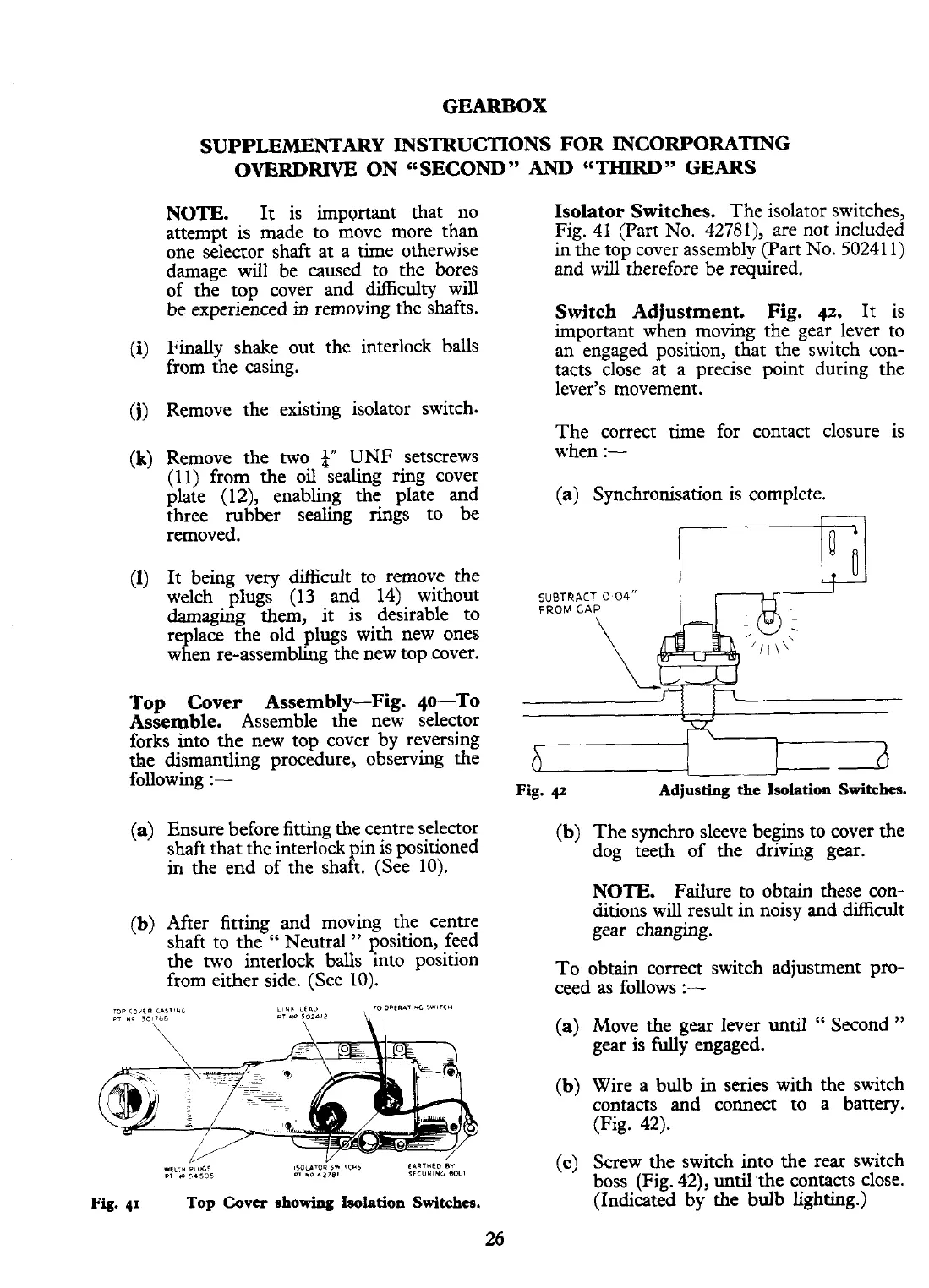
Switch Adjustment. Fig.
42.
It
is
important when moving the gear lever to
an engaged position, that the switch con-
tacts close at a precise point during the
lever's movement.
The correct time for contact closure is
when
:-
(a) Synchronisation is complete.
Fig.
42
Adjusting
the
Isolation Switches.
(b) The synchro sleeve begins to cover the
dog teeth of the driving gear.
NOTE. Failure to obtain these con-
ditions will result in noisy and difficult
gear changing.
To obtain correct switch adjustment pro-
ceed as follows
:-
(a) Move the gear lever until
"
Second
"
gear is fully engaged.
(b) Wire a bulb in series with the switch
contacts
and
connect to a battery.
(Fig. 42).
(c) Screw the switch into the rear switch
boss (Fig.
42), until the contacts close.
(Indicated by the bulb lighting.)