FRAME
UNIT
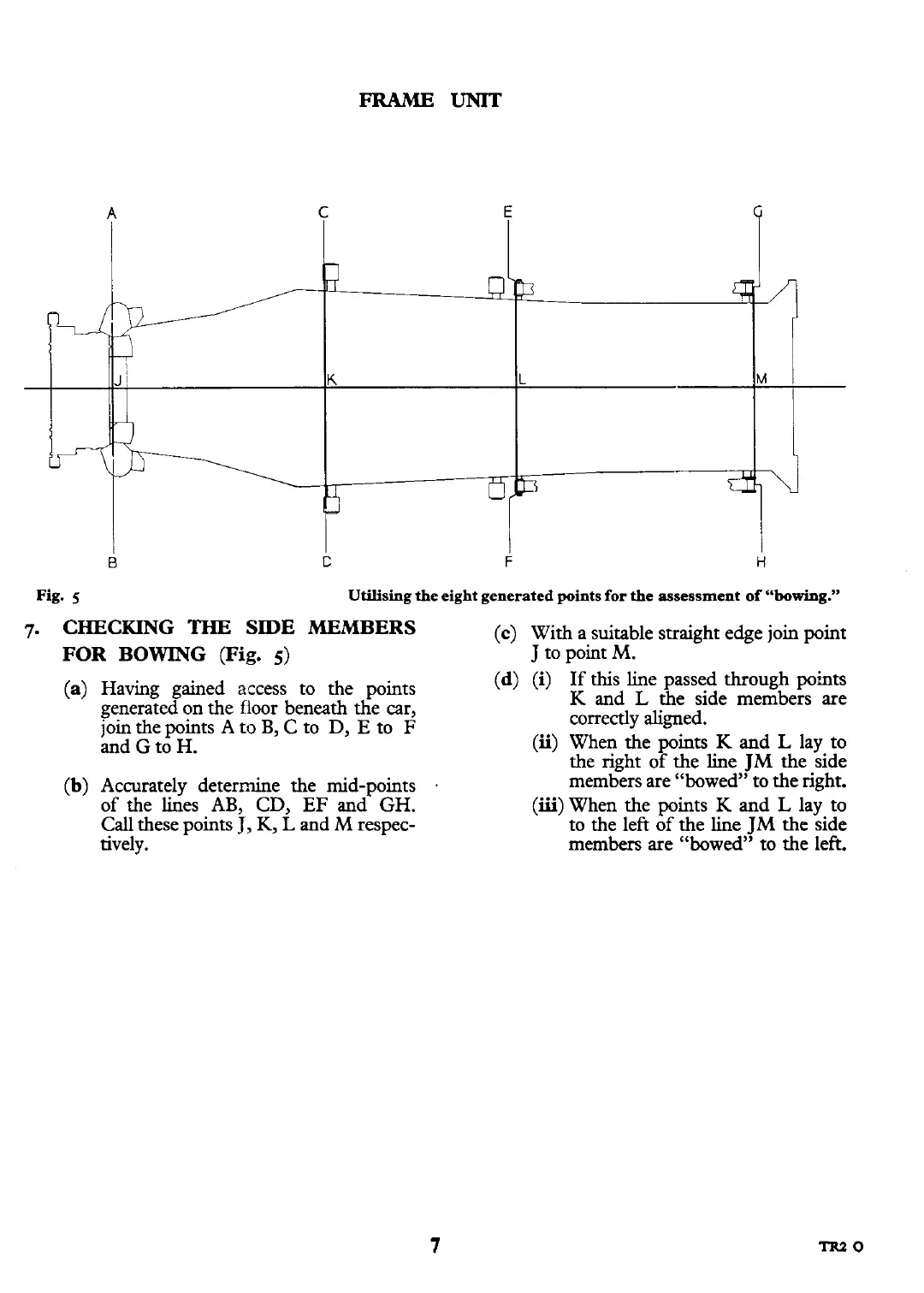
Fig.
5
Utilising the eight generated points
for
the assessment
of
"bowing."
7.
CHECKING
THE
SIDE MEMBERS
(c)
With a suitable straight edge join point
FOR BOWING
(Fig.
5)
J
to point
M.
(a)
Having gained access to the points
(d)
(i)
If this line passed through points
generated on the fioor beneath the car,
K and
L
the side members are
join the points A
to
B,
C to D,
E
to
F
correctly aligned.
and
G
to H.
(ii)
When the points K and
L
lay to
the right of the line
TM
the side
(b)
Accurately determine the mid-points
.
membYers are "bowed';to the right.
of the lines AB, CD,
EF
and GH.
(iii)
When the points K and
L
lay to
Call these points
J,
K,
L
and
M
respec- to the left of the line
JM
the side
tively. members are "bowed" to the left.