BODY
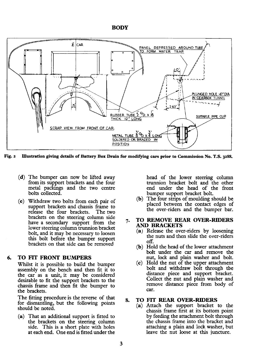
Fig.
2
Illustration
giving
details
of Battery Box
Drain
for modifying
cars
prior to Commission No.
T.S.
3288.
3
(d)
The bumper can now be lifted away
from its support brackets and the four
metal packings and the two centre
bolts collected.
(e)
Withdraw two bolts from each pair of
support brackets and chassis frame to
release the four brackets. The two
brackets on the steering column side
have a secondary support from the
lower steering column trunnion bracket
bolt, and it may be necessary to loosen
this bolt before the bumper support
brackets on that side
can
be removed
6.
TO
FIT
FRONT BUMPERS
Whilst it is possible to build the bumper
assembly on the bench and then fit it to
the car as a unit, it may be considered
desirable to fit the support brackets to the
chassis frame and then fit the bumper to
the brackets.
The fitting procedure is the reverse of that
for dismantling, but the following points
should be noted.
(a)
That an additional support is fitted to
the brackets on the steering column
side. This is a short plate with holes
at each end. One end is fitted under the
head of the lower steering column
trunnion bracket bolt and the other
end under the head of the front
bumper support bracket bolt.
(b)
The four strips of moulding should be
placed between the contact edges of
the over-riders and the bumper bar.
7.
TO REMOVE REAR OVER-RIDERS
AND
BRACKETS
(a)
Release the over-riders by loosening
the nuts and then slide the over-riders
off.
(b)
Hold the head of the lower attachment
bolt under the
car
and remove the
nut, lock and plain washer and bolt.
(c)
Hold the nut of the upper attachment
bolt and withdraw bolt through tbe
distance piece and support bracket.
Collect the nut and plain washer and
remove distance piece from body of
car.
8.
TO
FIT
REAR OVER-RIDERS
(a)
Attach the support bracket to the
chassis frame first at its bottom point
by feeding the attachment bolt through
the chassis frame into the bracket and
attaching a plain and lock washer, but
leave the nut loose at this juncture.