FUEL
SYSTEM
3.
TO FIT PETROL
TANK
After ensuring that the tank is perfectly
sound and clean, it
can
be replaced in the
car.
The recommended method of testing the
tank is to clean the exterior with a wire
brush, blank off the filler pipe and
all
but
one union then connect to a compressed
air
line. Submerge the tank in water and
slowly
fill
the tank with
air.
Faults will
clearly be seen by escaping
air.
The replacement of the tank is the reversal
of the removal.
It
is a wise precaution to run the engine
for a short time to observe the connections
for leaks before replacing the
trim.
4.
PETROL GAUGE
Description
The petrol gauge comprises two com-
ponents, the dashboard meter and the tank
unit.
The dashboard meter consists of a metal
case, containing the coils and shaped knob
pieces which operate the gauge, also a
bezel with a calibrated dial and indicator
needle.
The coils are wound on
bakelite bobbins
with soft iron cores and the shaped knob
pieces exert a magnetic force on a
pivotted iron armature which is attached to
the indicator. The magnetic force of the
two coils cause the armature to be deflected
The voltage across each coil is varied
according to the position of the tank unit
float arm.
The tank unit consists of a float and float
arm mounted in a zinc based die casting.
The float arm carries a contact arm which
travels over a resistance wound on a
bake-
lite former. The contact arm takes up a
position according to the quantity of petrol
in the tank and so varies the current
through to the meter.
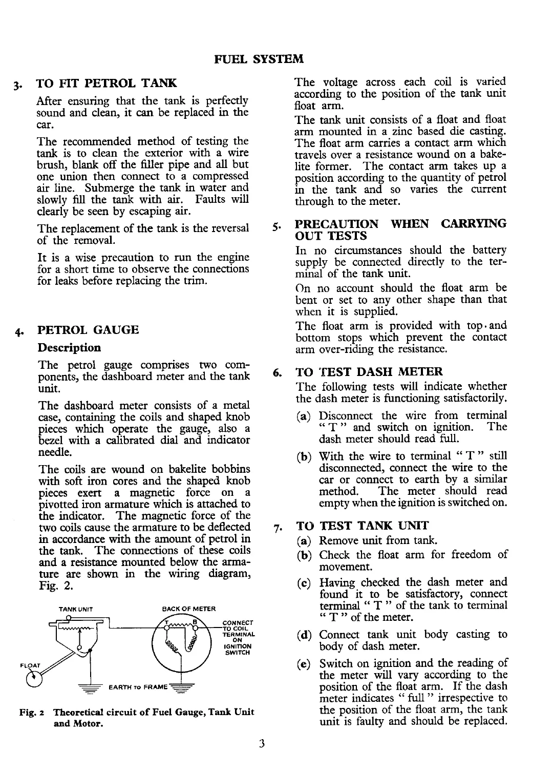
in
accordance with the amount of petrol in
the
tank.
The connections of these coils
and
a
resistance mounted below the arma-
ture are shown
in
the wiring
diagram,
Fig.
2.
TANK UNIT BACK
OF
METER
CONNECT
TO COIL
TERMINAL
ON
IGNITION
SWITCH
Fig.
2
Theoretical
circuit
of
Fuel Gauge,
Tank
Unit
and
Motor.
5.
PRECAUTION WHEN CARRYING
OUT TESTS
In no circumstances should the battery
supply be connected directly to the ter-
minal of the tank unit.
On no account should the float arm be
bent or set to any other shape than that
when it is supplied.
The float arm is provided with top- and
bottom stops which prevent the contact
arm over-riding the resistance.
6.
TO
TEST DASH METER
The following tests will indicate whether
the dash meter is functioning satisfactorily.
(a)
Disconnect the wire from terminal
"
T
"
and switch on ignition.
The
dash meter should read
full.
(b)
With the wire to terminal
"
T
"
still
disconnected, connect the wire to the
car or connect to earth by a similar
method. The meter should read
empty when the ignition is switched on.
7.
TO
TEST TANK UNIT
(a)
Remove unit from tank.
(b)
Check the float arm for freedom of
movement.
(c)
Having checked the dash meter and
found it to be satisfactory, connect
terminal
"
T
"
of the tank to terminal
"
T
"
of the meter.
(d)
Connect tank unit body casting to
body of dash meter.
(e)
Switch on ignition and the reading of
the meter will vary according to the
position of the float arm. If the dash
meter indicates
"
full
"
irrespective to
the position of the float arm, the tank
unit is faulty and should be replaced.
 Loading...


