FUEL
SYSTEM
(e)
Push the rod to the left of the car,
right it can be freed from the left.
this
will
eject the accelerator pedal in
hand bearing.
to the interior of the car and also
(f)
The bearings and housings can b~
free the shaft from its right-hand
removed by withdrawing the eigh
bearing. On drawing the shaft to the
self tapping screws (four each bearing;
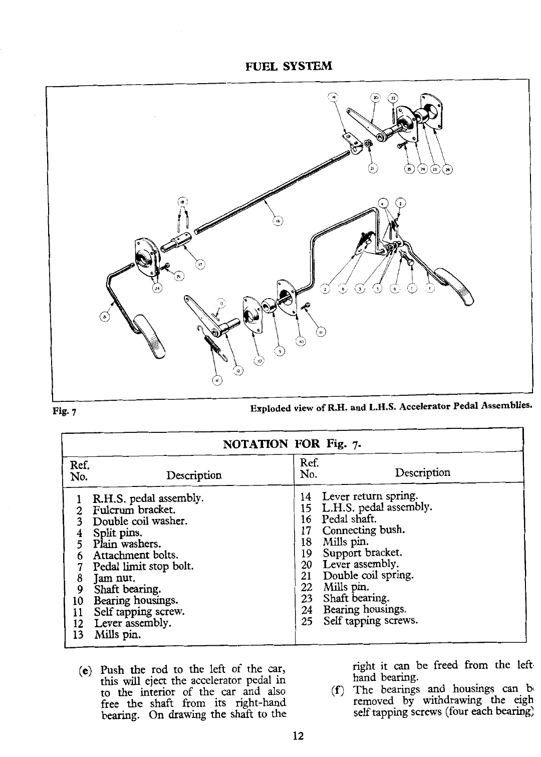
NOTATION FOR
Fig.
7.
Ref.
No.
Description
1 R.H.S. pedal assembly.
2
Fulcrum
bracket.
3
Double coil washer.
4
Split pins.
5
Plain
washers.
6
Attachment bolts.
7
Pedal limit stop bolt.
8
Jam
nut.
9 Shaft bearing.
10 Bearing housings.
11 Self tapping screw.
12 Lever assembly.
13
Mills pin.
Ref.
No.
Description
14 Lever return spring.
15 L.H.S. pedal assembly.
16
Pedal shaft.
17 Connecting bush.
18 Mills pin.
19 Support bracket.
20 Lever assembly.
21 Double coil spring.
22 Mills pin.
23 Shaft bearing.
24 Bearing
housings.
25 Self tapping screws.