FUEL
SYSTEM
THE
S.U.
CARBURETTOR
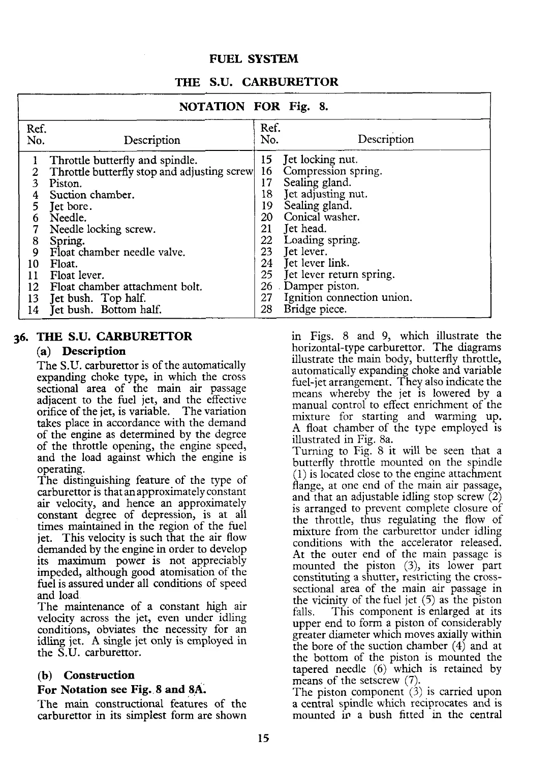
NOTATION FOR Fig.
8.
Ref.
No.
Description
1 Throttle butterfly and spindle.
2 Throttle butterfly stop and adjusting screu
3
Piston.
4 Suction chamber.
5 Jet bore.
6
Needle.
7 Needle locking screw.
-
8
Spring.
9
Float chamber needle valve.
10 Float.
11 Float lever.
12 Float chamber attachment bolt.
13 Jet bush. Top half.
14 Jet bush. Bottom half.
36.
THE
S.U.
CARBURETTOR
(a)
Description
The
S.U.
carburettor is of the automatically
expanding choke type,
in
which the cross
sectional area of the main air passage
adjacent to the fuel jet, and the effective
orifice of the jet, is variable. The variation
takes place in accordance with the demand
of the engine as determined by the degree
of the throttle opening, the engine speed,
and the load against which the engine is
operating.
The distinguishing feature of the type of
carburettor is that anapproximately constant
air
velocity, and hence an approximately
constant degree of depression, is at all
times maintained in the region of the fuel
jet. This velocity is such that the air flow
demanded by the engine in order to develop
its maximum power is not appreciably
impeded, although good atomisation of the
fuel is assured under all conditions of speed
and load
The maintenance of a constant high air
velocity across the jet, even under idling
conditions, obviates the necessity for an
idling jet.
A
single jet only is employed in
the S.U. carburettor.
(b)
Cons~ruction
For Notation see Fig.
8
and 8A.
The main constructional features of the
carburettor in its simplest form are shown
-
Ref.
No. ~escription
15 Jet locking nut.
16 Compression spring.
17 Sealing gland.
18 Jet adjusting nut.
19 Sealing gland.
20 Conical washer.
21 Jet head.
22 Loading spring.
23 Jet lever.
24 Jet lever
link.
25 Jet lever return spring.
26
.
Damper piston.
27 Ignition connection union.
28 Bridge piece.
in
Figs.
8
and
9,
which illustrate the
horizontal-type carburettor. The diagrams
illustrate the main body, butterfly throttle,
automatically expanding choke and variable
fuel-jet arrangement. They also indicate the
means whereby the jet is lowered by a
manual control to effect enrichment of the
mixture for starting and warming up.
A
float chamber of the type employed is
illustrated in Fig. 8a.
Turning to Fig. 8 it will be seen that a
butterfly throttle mounted on the spindle
(1) is located close to the engine attachment
flange, at one end of the main air passage,
and that an adjustable idling stop screw (2)
is arranged to prevent complete closure of
the throttle, thus regulating the flow of
mixture from the carburettor under idling
conditions with the accelerator released.
At the outer end of the main passage is
mounted the piston
(3),
its lower part
constituting a shutter, restricting the cross-
sectional area of the main air passage in
the vicinity of the fuel jet
(5)
as the piston
falls. This component is enlarged at its
upper end to form a piston of considerably
greater diameter which moves axially within
the bore of the suction chamber (4) and at
the bottom of the piston is mounted the
tapered needle
(6)
which is retained by
means of the setscrew
(7).
The piston component
(3)
is carried upon
a central spindle which reciprocates
and
is
mounted
in
a bush fitted
in
the central
 Loading...


