FUEL
SYSTEM
kf.
Go. Description
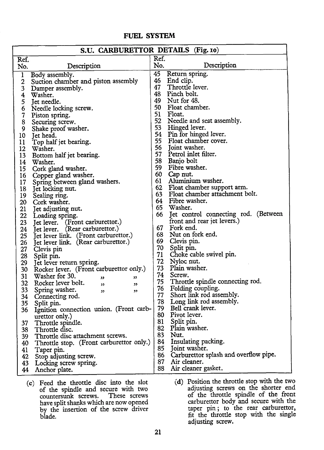
:5
Return spring.
16
End clip.
L7 Throttle lever.
L8
Pinch bolt.
L9 Nut for 48.
iO
Float chamber.
jl
Float.
i2 Needle and seat assembly.
53 Hinged lever.
54 Pin for hinged lever.
55 Float chamber cover.
56 Joint washer.
57 Petrol inlet filter.
58 Banjo bolt
59 Fibre washer.
50
Cap
nut.
51
Aluminium
washer.
62 Float chamber support arm.
63 Float chamber attachment bolt.
64 Fibre washer.
65 Washer.
66 Jet control connecting rod. (Between
front and rear jet levers.)
67 Fork end.
68 Nut on fork end.
69
Clevis pin.
70 Split pm.
71 Choke cable swivel pin.
72
Nyloc nut.
73 Plain washer.
74 Screw.
75 Throttle spindle connecting rod.
76 Folding coupling.
77 Short
link
rod assembly.
78 Long
link
rod assembly.
79 Bell crank lever.
80 Pivot lever.
81 Split pin.
82 Plain washer.
S.U.
CARBURETTOR
Ref.
No. Description
1 Body assembly.
2 Suction chamber and piston assembly
3 Damper assembly.
4 Washer.
5 Jet needle.
6 Needle
locking screw.
7 Piston spring.
8 Securing screw.
9 Shake proof washer.
10 Jet head.
11 Top half jet bearing.
12 Washer.
13 Bottom half jet bearing.
14 Washer.
15 Cork gland washer.
16 Copper gland washer.
17 Spring between gland washers.
18 Jet locking nut.
19 Sealing ring.
20 Cork washer.
21 Jet adjusting nut.
22 Loading spring.
23 Jet lever. (Front carburettor.)
24 Jet lever. (Rear carburettor.)
25 Jet lever
link.
(Front carburettor.)
26 Jet lever
link.
(Rear carburettor.)
27 Clevis pin
28 Split pin.
29
Jet lever return spring.
30 Rocker lever. (Front carburettor only.)
31 Washer for 30.
YY
YY
32 Rocker lever bolt.
M
9)
33 Spring washer.
yy
9)
34 Connecting rod.
35 Split pin.
36 Ignition connection union. (Front carb-
urettor only.)
37 Throttle
S
indle.
(E
38 Throttle sc.
39
Throttle disc attachment screws.
40 Throttle stop. (Front carburettor only.)
41 Taper pin.
42 Stop
adjusting screw.
43 Locking screw spring.
44
Anchor plate.
(c)
Feed the throttle disc into the slot
83 Nut.
84 Insulating packing.
85 loint washer.
DETAILS
(Fig.
10)
I
E
4
4
4
4
4
C
C
r
z
1
l
1
1
1
1
(
I
I
l
86 l~arburettor splash and overflow pipe.
87 Air cleaner.
88
Air
cleaner gasket.
of the spindle and secure
with
two
countersunk screws. These screws
have split shanks which are now opened
by the insertion
of
the
screw driver
blade.
(d)
Position the throttle stop with the two
adjusting screws on the shorter end
of the throttle spindle of
the
front
carburettor body and secure
with
the
taper pin
;
to
the
rear carburettor,
fit
the throttle stop
with
the single
adjusting screw.
 Loading...


