BRAKES
(h)
Position the cover plate on the body
in such a manner that the filler cap
is nearer the outlet ports. This
will
ensure the jets of fluid from the
cylinder will impinge upon the plate
and so avoid possible leakage through
the filler cap. Ensure that the joint
washer and filler cap sealing ring are
in good order and that the vent hole
is clear.
(i)
Test the assembly by filling the tank
with Lockheed Hydraulic Brake Fluid
to within 1" of the filler orifice top.
Then push the piston inward and it
should return without any assistance
;
after a few aplications fluid should be
ejected from the outlet connections.
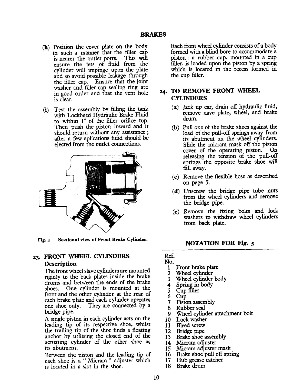
Fig.
q
Sectional
view
of
Front
Brake
Cylinder.
FRONT
WHEEL
CYLINDERS
Description
The front wheel slave cylinders are mounted
rigidly to the back plates inside the brake
drums and between the ends of the brake
shoes. One cylinder is mounted at the
front and the other cylinder at the
rear
of
each brake plate and each cylinder operates
one shoe only. They are connected by a
bridge pipe.
A
single piston
in
each cylinder acts on the
leading tip of its respective shoe, whilst
the trailing tip of the shoe finds a floating
anchor by utilising the closed end of the
actuating cylinder of the other shoe as
its abutment.
Between the piston and the leading tip of
each shoe is a
"
Micrarn" adjuster which
is located
in
a slot in the shoe.
Each front wheel cylinder consists of a body
formed with a blind bore to accommodate a
piston
:
a rubber cup, mounted in a cup
filler, is loaded upon the piston by a spring
which is located in the recess formed in
the cup filler.
24.
TO REMOVE FRONT
WHEEL
CYLINDERS
(a)
Jack up
car,
drain off hydraulic fluid,
remove nave plate, wheel, and brake
drum.
(b)
Pull one of the brake shoes against the
load of the pull-off springs away from
its abutment on the wheel cylinders.
Slide the
micram mask off the piston
cover of the operating piston. On
releasing the tension of the pull-off
springs the opposite brake shoe
wiU
fall away.
(c)
Remove the flexible hose as described
on page 5.
(d)
Unscrew the bridge pipe tube nuts
from the wheel cylinders and remove
the bridge pipe.
(e)
Remove the fixing bolts and lock
washers to withdraw wheel cylinders
from back plate.
NOTATION
FOR Fig.
5
Ref.
No.
1 Front brake late
c!
2
Wheel cylin er
3 Wheel cylinder body
4
Spring in body
5
Cup filler
6
Cup
7
Piston assembly
8 Rubber seal
9
Wheel cylinder attachment bolt
10 Lock washer
11 Bleed screw
12 Bridge pipe
13 Brake shoe assembly
14
Micrarn
adjuster
15
Micram
adjuster mask
16 Brake shoe pull off spring
17
Hub grease catcher
18 Brake
drum
 Loading...


