REAR
AXLE
I.
GENERAL
A
new rear axle assembly, Part No. 302177,
bearing the Serial No. 13511, was jntro-
duced at Commission No. 13046 and fitted
on all subsequent cars.
The major differences incorporated in the
new axle include new half shaft and hub
assemblies, a thrust button mounted on the
differential cross-pin and adjustable taper
roller hub bearings, as shown in Fig. 1.
The sectioned insert views indicate the axle
arrangement for cars prior to this change.
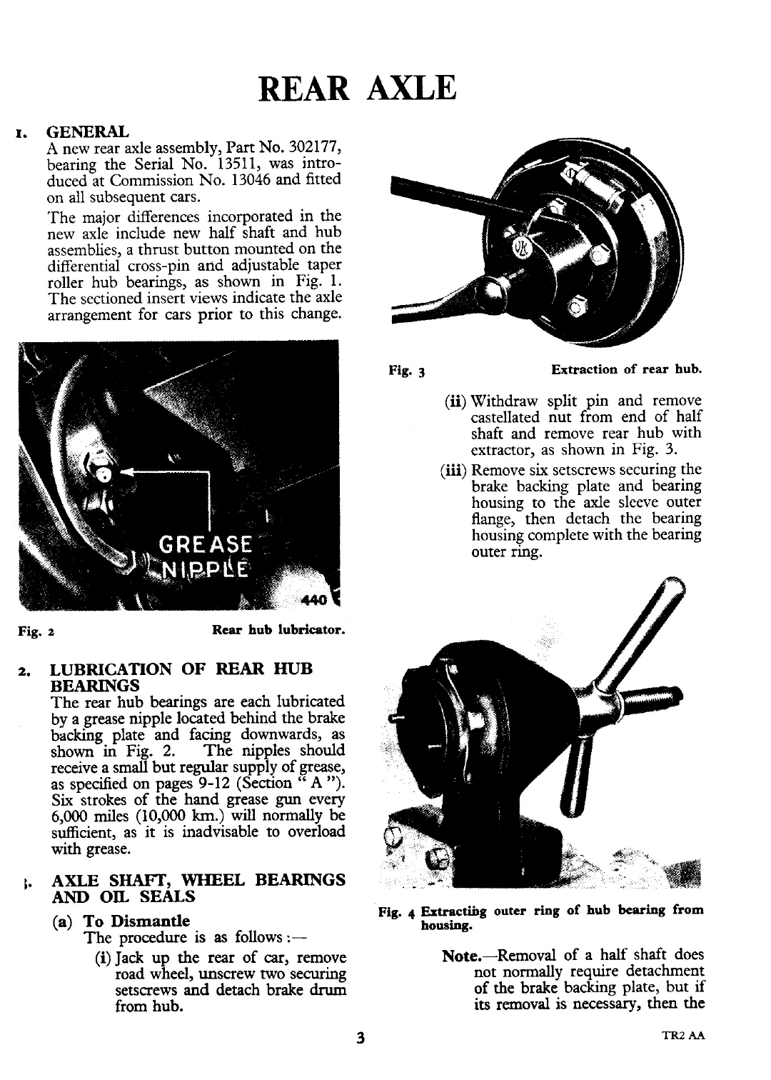
Fig.
3
Extraction of rear hub.
(ii) Withdraw split pin and remove
castellated nut from end of half
shaft and remove rear hub with
extractor, as shown in Fig.
3.
(iii)
Remove six setscrews securing the
brake backing plate and bearing
housing to the axle sleeve outer
flange, then detach the bearing
housing complete with the bearing
outer ring.
Fig.
t
Rear
hub lubricator.
2.
LUBRICATION OF
REAR
HUB
BEARINGS
The rear hub bearings are each lubricated
by a grease nipple located behind the brake
backing plate and facing downwards, as
shown in Fig. 2. The nipples should
receive a small but regular supply of grease,
as specified on pages
9-12
(Section
"
A
").
Six strokes of the hand grease
gun
every
6,000 miles (10,000
km.)
will normally be
sufficient, as it is inadvisable to overload
with grease.
1.
AXLE SHAFT,
WHEEL
BEARINGS
AND
OIL
SEALS
(a)
To
Dismantle
The procedure
is
as follows
:-
(i) Jack up the
rear
of
car,
remove
road wheel, unscrew
two
securing
setscrews
and
detach brake
drum
from hub.
Fig.
4
Extractii~g
outer
ring
of hub
bearing
from
housing.
Note.-Removal of a half shaft does
not normally require detachment
of the brake backing plate, but
if
its
removal is necessary, then the