BRAKES
Instead of pushing the pistons to the
bottom of the bore withdraw them
from the caliper body, taking great
care not to damage the bores. The
sealing rings may then be removed by
inserting a blunt tool under the seals
and prising out, taking care not to
damage the locating grooves.
Ex-
amine the bores and pistons carefully
for any signs of abrasion or "scuffing."
No attempt should be made to remove
the end plug retainer, as this is screwed
in tightly by mechanical means.
It is important that in cleaning the
components no petrol, paraffin,
tri-
chlorethylene or mineral
fluid
of any
kind
should be used. Clean with
methylated spirits and allow to vapor-
ise, leaving the component clean and
dry.
After cleaning and examining, lubricate
the working surfaces of the bores .md
piston with clean genuine
Gi.
g
Crimson Brake and Clutch Fluid.
Assembling
Fit new rubber seals into the grooves
of caliper cylinder bore. Locate the
rubber dust cover with the projecting
lip into the groove provided which is
the outer one of the cylinder bore.
Insert the piston, closed end first, into
%-
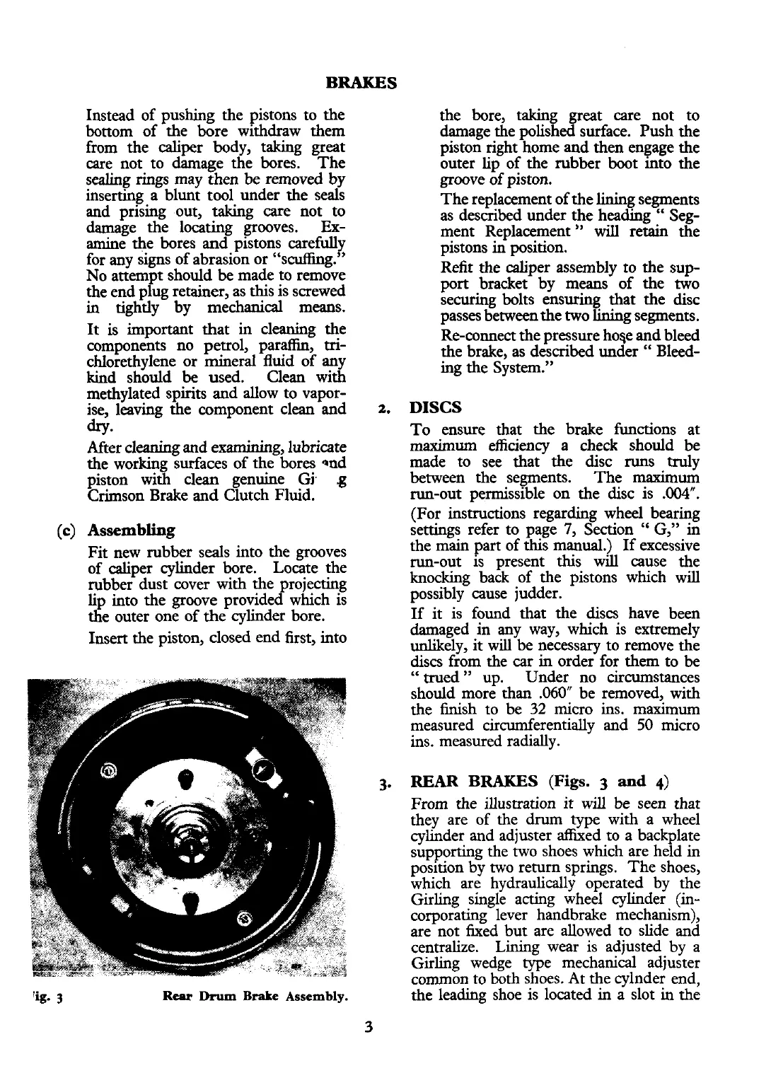
3
Rear
Drum
Brake Assembly.
the bore, taking great care not to
damage the polished surface. Push the
piston right home and then engage the
outer lip of the rubber boot into the
groove of piston.
The replacement of the lining segments
as described under the heading
"
Seg-
ment Replacement
"
will
retain the
pistons in position.
Refit the caliper assembly to the sup-
port bracket by means of the two
securing bolts ensuring that the disc
passes between the two lining segments.
Re-connect the pressure
hose and bleed
the brake, as described under
"
Bleed-
ing the System."
2.
DISCS
To ensure that the brake functions at
maximum efficiency a check should be
made to see that the disc runs truly
between the segments. The maximum
run-out permissible on the disc is
.004".
(For instructions regarding wheel bearing
settings refer to page
7,
Section
"
G," in
the main part of this manual.) If excessive
run-out is present this will cause the
knocking back of the pistons which will
possibly cause judder.
If it is found that the discs have been
damaged in any way, which is extremely
unlikely, it will be necessary to remove the
discs from the car in order for them to be
"
trued
"
up. Under no circumstances
should more than
.060fr
be removed, with
the finish to be
32
micro ins.
maximum
measured circumferentially and
50
micro
ins. measured radially.
3.
REAR BRAKES
(Figs.
3
and
4)
From the illustration it will
be
seen that
they are of the drum type with a wheel
cylinder and adjuster &ed to a backplate
supporting the two shoes which are held in
position by two return springs. The shoes,
which are hydraulically operated by the
Girling single acting wheel cylinder (in-
corporating lever handbrake mechanism),
are not fixed but are allowed to slide and
centralize. Lining wear is adjusted by a
Girling wedge type mechanical adjuster
common to both shoes. At the cylnder end,
the leading shoe is located in a slot in the
 Loading...


