BRAKES
RUNNING
ADJUSTMENTS
The front disc brakes are entirely self-
adjusting. The rear brakes are adjusted
for lining wear at the brakes themselves,
and on no account should any alteration be
made to the hand brake cable for this pur-
pose (Fig.
l).
One common adjuster is provided for each
brake assembly. Adjustment of both rear
wheels is identical.
Release the handbrake and jack up the
m.
Turn the square end of the adjuster on the
outside of each rear brake backplate
in
a
clockwise direction
until
a resistance is
felt, then slacken back two clicks, when the
drum
should rotate freely.
Immediately after fitting replacement shoes
it is advisable to slacken one further click
to allow for possible lining expansion,
reverting to normal adjustment afterwards.
BOOT
RETAINING BAND
RUBBER BOOT
MASTER CYLINDER
JAW
END.
VALVE SPACER
PLUNGER
SEAL.
\
END
SEAL
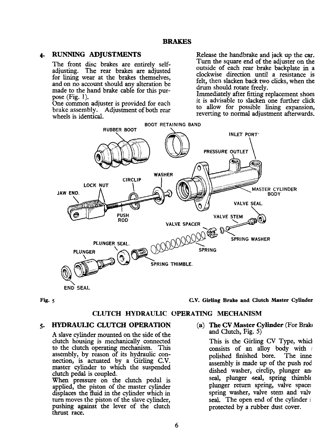
Fig.
5.
5
C.V.
Guling
Brake
and
Clutch Master Cylinder,
CLUTCH
HYDRAULIC
OPERATING
MECHANISM
HYDRAULIC CLUTCH
OPERATION
(a)
The
CV
fister
Cylinder
(For Brakc
and Clutch, Fig.
5)
A
slave cylinder mounted on the side of the
clutch housing is mechanically connected
to the clutch operating mechanism. This
assembly, by reason of its hydraulic con-
nection, is actuated by a Girling
C.V.
master cylinder to which the suspended
dutch pedal is coupled.
When pressure on the clutch pedal is
applied,
the
piston of the master cylinder
displaces the
fluid
in the cylinder which in
turn
moves the piston of the slave cylinder,
pushing against the lever of the dutch
thrust race.
This is the Girling
CV
Type, whicl
consists of an alloy body with
:
polished finished bore. The inne
assembly is made up of the push rod
dished washer,
circlip, plunger
an(
seal, plunger
-seal,
spring thirnblt
plunger return spring, valve space]
spring washer, valve stem and valv
seal. The open end of the cylinder
I
protected by a rubber dust cover.