ENGINE
and the second situated below the inlet
and exhaust manifold
in
the cylinder
block.
(d)
Drain off the oil from the engine and
gearbox.
(e)
Disconnect the head and side light
cables at their snap connectors. Re-
move the bolts from the top brackets
and the bolt
in
the centre of the
cowling, this holds the bonnet lock
connecting cable, release cable control
at one side. Remove the twelve set-
screws (six per side) situated under the
wheel arches. Remove the starting
handle bracket and the steady rods
from under the
cow- and
finally
the
nut and bolt from the steady plate.
(f)
To remove radiator disconnect top
and bottom hoses, release the tie rods
at the top and the bolts one either side
at the base of the unit.
(g)
Disconnect the lever
Mqes
at the
foremost carburettor
;
disconnect the
inner and outer cables of the choke
control and the
fuel feed pipes at their
banjo unions. Remove the carburet-
tors from the manifold by undoing the
four nuts-two at each flange.
(h)
Remove the horns from their brackets
by first removing the four fixing bolts
(two to each horn). There is no need
to disconnect the horns from their
cables. Disconnect dynamo leads and
remove
dvnarno from its bracket and
remove fah belt.
Remove front chassis cross
tube
by
removal of three nuts and bolts at each
flange.
Remove the three nuts and washers at
the exhaust flange and break the joint.
Disconnect the flexible fuel pipe at
the petrol tap, the oil pressure gauge
pipe, starter motor cable, L.T. lead at
the coil, the tachometer drive at
distributor pedestal and withdraw the
water temperature gauge bulb.
To remove the seats, first remove the
cushions and unscrew the sixteen nuts
eight to each seat) thus releasing the
rame from the runners; it
can
then
i
be
lifted out.
(m)
Free the rubber gear lever grommet by
the removal of three self-tapping
screwsfrom the gearbox cover pressing
and remove the latter by unscrewing
the thirteen setscrews, hidden by the
trim and floor covering.
(n)
Remove the gear lever with grommet
by loosening the locknut and un-
screwing the lever.
(0)
Remove the speedometer drive, the
overdrive cable at the snap connector
and the starter motor by removing two
nuts and bolts.
(p)
Drain the clutch hydraulic system.
Disconnect the bundy tubing at the
flexible hose at the left-hand side
chassis member whilst holding the
hexagon on the hose. Still holding the
hexagon remove
the hose securing nut
and shakeproof washer; the flexible
hose can now be withdrawn from its
bracket.
(q)
Uncouple the propeller shaft by re-
moving the four nuts and bolts securing
the two flanges. Remove the two nuts
holding the gearbox to the chassis
frame.
(r)
Remove the four nuts and bolts (two
each side) securing the engine mount-
ings to the chassis.
(S)
Fit slings to engine and lift out in a
"
nose up
"
position, as shown in
Fig. 31.
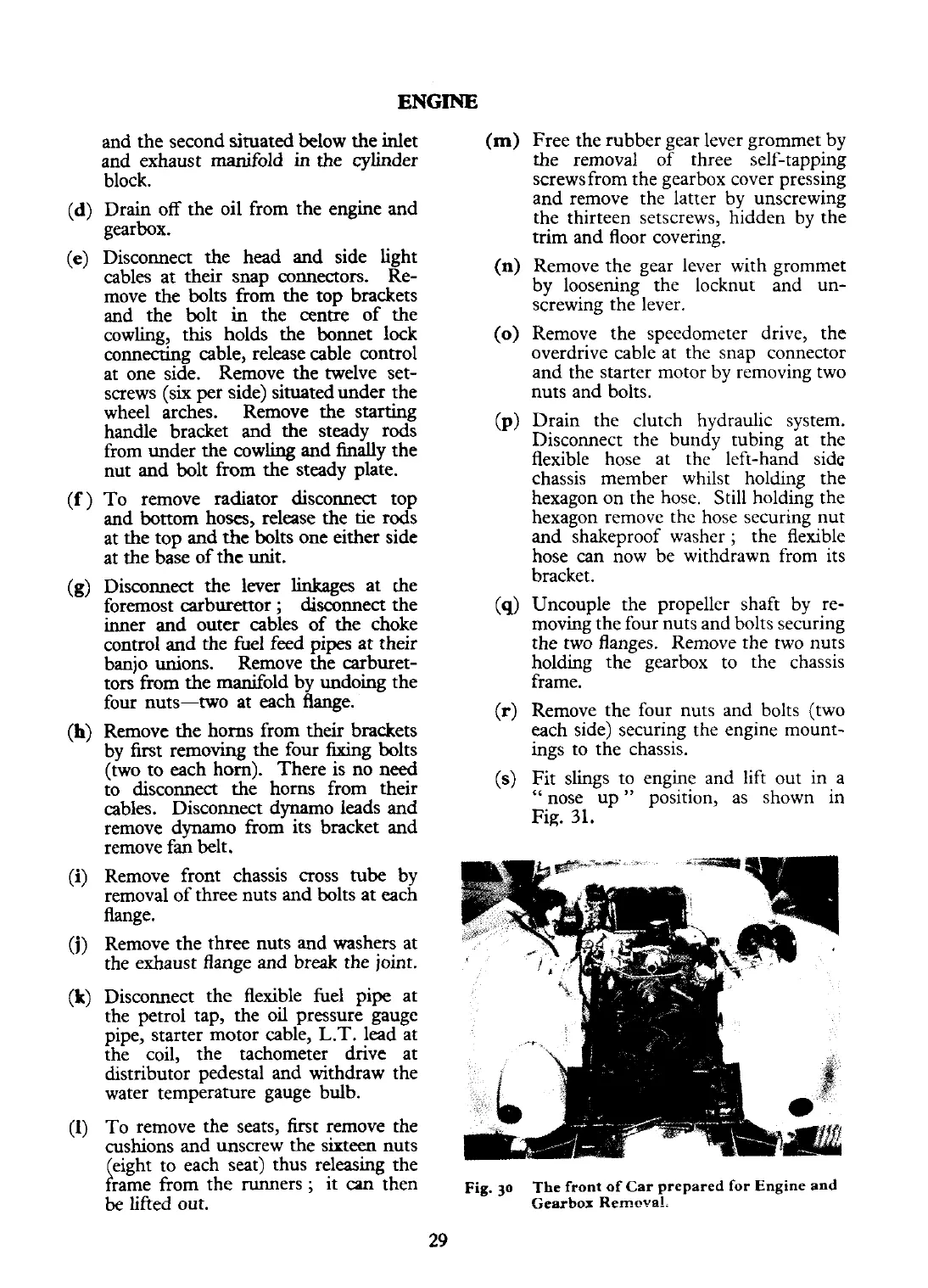
Fig.
30
The front of Car prepared for Engine and
Gearbox Remeva!.
 Loading...


