ENGINE
which
aligns
with
L.H.
rubber mount-
ing attachment nut.
(xxiii)
The machined faces on the combustion
head and the upper flanges of the
cylinder sleeves; which contact the
combustion head gasket, should be
lightly coated with
"
Wellseal
"
sealing
compound. A substitute compound,
which retains its plasticity, may be
used
if
"
Wellseal
"
is not available.
This sealin is necessary to ensure a
proper life
f
or the gasket.
Assemble the valves and springs to the
combustion head (see "To De-
carbonise," page 25) and fit the assembly
to the block, tightening the ten nuts
and washers down as shown in Fig.
28. Fit push rods in the chambers.
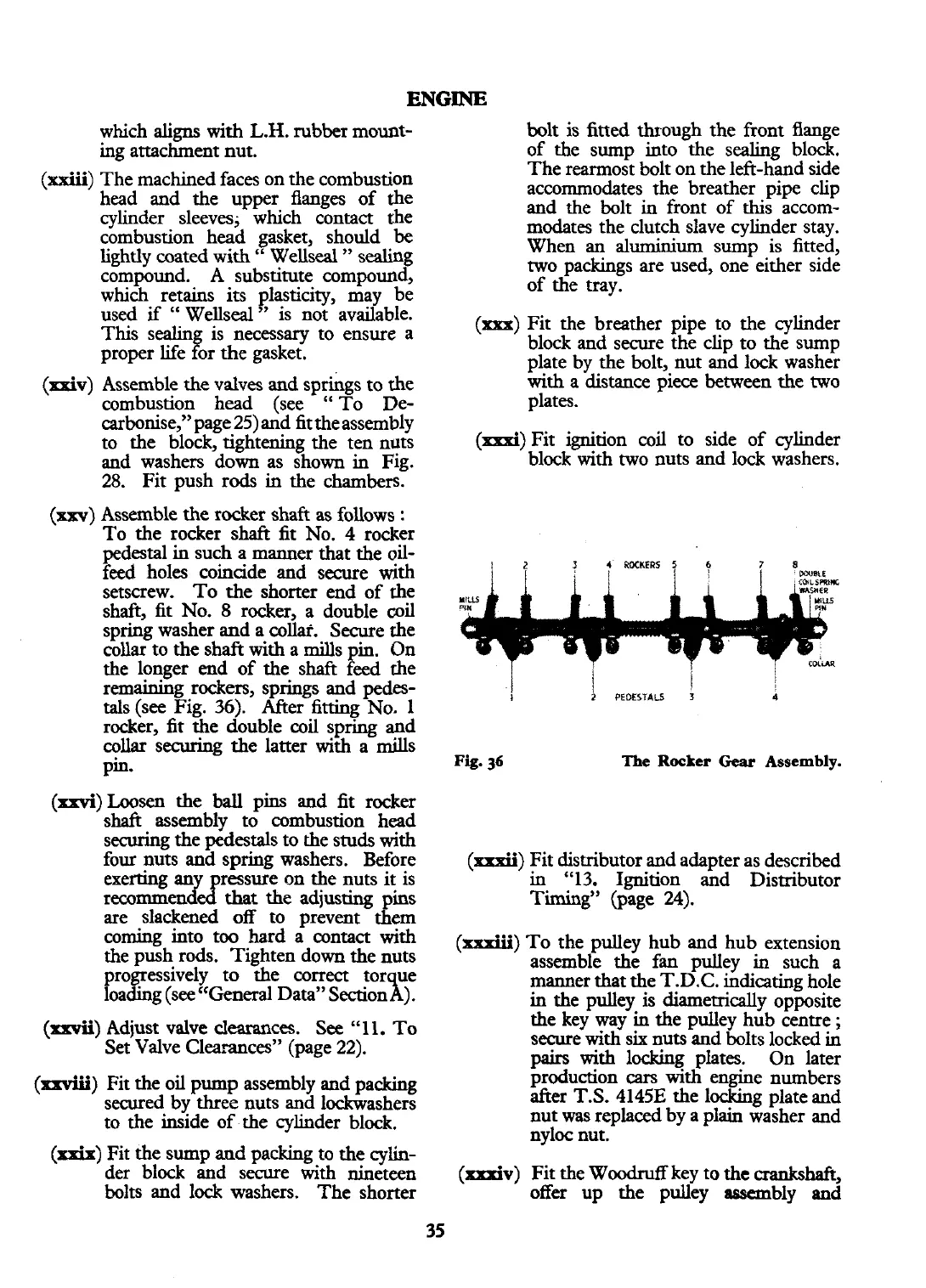
Assemble the rocker shaft as follows
:
To the rocker shaft fit No. 4 rocker
pedestal in such a manner that the oil-
feed holes coincide and secure
with
setscrew. To the shorter end of the
shaft, fit No.
8
rocker, a double
coil
spring washer
and
a collaf. Secure the
collar to the shaft
with
a mills in. On
the longer end of the shaft
4
eed the
remaining rockers, springs and pedes-
tals (see Fig.
36).
After fitting No.
1
rocker, fit the double coil spring and
collar securing the latter with a mills
pin.
(xxvi)Loosen
the
ball
pins and fit rocker
shaft assembly to combustion head
securing the pedestals to the studs with
four nuts and spring washers. Before
exerting an
ressure on the nuts it is
recommen~d
that
the
adjusting pins
are slackened off to prevent them
coming into too hard a
contact
with
the push rods. Tighten down the nuts
correct tor ue
Data" Section
X
).
(d)
Adjust valve clearances. See
"1 1.
To
Set Valve Clearances" (page 22).
(xxviii)
Fit the oil pump assembly and packing
secured by three nuts and lockwashers
to the inside of the cylinder block.
(xxix)
Fit the sump and packing to the cylin-
der block and secure with nineteen
bolts and lock washers. The shorter
bolt is fitted through the front flange
of the sump into the sealing block.
The rearmost bolt on the left-hand side
accommodates the breather pipe clip
and the bolt in front of this accom-
modates the clutch slave cylinder stay.
When an aluminium sump is fitted,
two
packings are used, one either side
of the tray.
(5)
Fit the breather pipe to the cylinder
block and secure the clip to the sump
plate by the bolt, nut and lock washer
with
a
distance piece between the two
plates.
(xxxi)
Fit ignition coil to side of cylinder
block
with
two nuts and lock washers.
Fig.
36
The
Rocker
Gear
Assembly.
(d)
Fit distributor and adapter as described
in "13. Ignition and Distributor
Timing" (page
24).
(xxxiii)
TO
the pulley hub and hub extension
assemble the fan pulley
in
such a
manner
that
the T.D.C. indicating hole
in the pulley
is
diametrically opposite
the key way in the pulley hub centre
;
secure with six nuts and bolts locked in
pairs
with
locking plates. On later
production cars
with
engine numbers
after T.S. 4145E the locking plate and
nut
was
replaced by a plain washer and
nyloc nut.
(xxxiv)
Fit the Woodruff key to
the
crankshaft,
offer up the pulley
assembly
and
 Loading...


