ELECTRICAL
EQUIPMENT
Inspection of Commutator
Disconnect the wiper at its terminals
and withdraw the three screws securing
the cover at the
commutator end.
Lift
off the cover. Clean the commutator,
using a petrol-moistened cloth, taking
care to remove any carbon dust from
between the commutator segments.
Inspection of
Brush
Gear
Check that the brushes bear freely on
the commutator. If they are loose or do
not make contact, a replacement ten-
sion spring is necessary. The brush
levers must be free on their pivots. If
they are stiff, they should be freed by
working them backwards and forwards.
Brushes which are considerably worn
must be replaced.
Motor Operates but does not
Transmit Motion to Spindles
-
Remove the gearbox cover.
A
push-
pull motion should be transmitted to
the inner cable of the flexible rack. If
the crosshead moves sluggishly be-
tween the guides, lightly smear a
small amount of medium grade engine
oil in the groove formed in the die-cast
housing.
When overhauling, the gearbox must
be lubricated by
packing it
with
a
grease of the zinc oxide base type.
2.
FLASHING LIGHT DIRECTION
INDICATORS
ELECTRIC
WINDTONE HORNS
-
Models
W614
and
W618
I.
GENERAL
Windtone horns de end for their operation
P.
on the vibration o
an
au
column, excited
at its resonant frequency, or a harmonic of
it, by an electrically energised diaphragm.
The horns are fitted in pairs, one horn
having a higher note than the other. The
horns differ in note by an interval of a
major third. Earlier fitment
WT614 and
later
WT618 horns are recognisable from
each other by the different shape of their
trumpet flares. High and low note horns
can
be distinguished by the letters
"
H
"
or
"
L
"
marked inside the trumpet flares.
(a)
Note of Horn Unsatisfactory or
Operation Intermittent
(i)
Check that the bolts securing the
horn bracket are tight and that the
body or flare of the horn does not
foul any other fixture. See that
any units fitted near the horn are
rigidly mounted, and do not vi-
brate when the horn is blown.
Examine the cables of the horn
circuit, renewing any that are
badly worn or chafed. Ensure
that all connections are tight, and
that the connecting eyelets or
nipples are firmly soldered to the
cables.
In the event of irregular operation of the
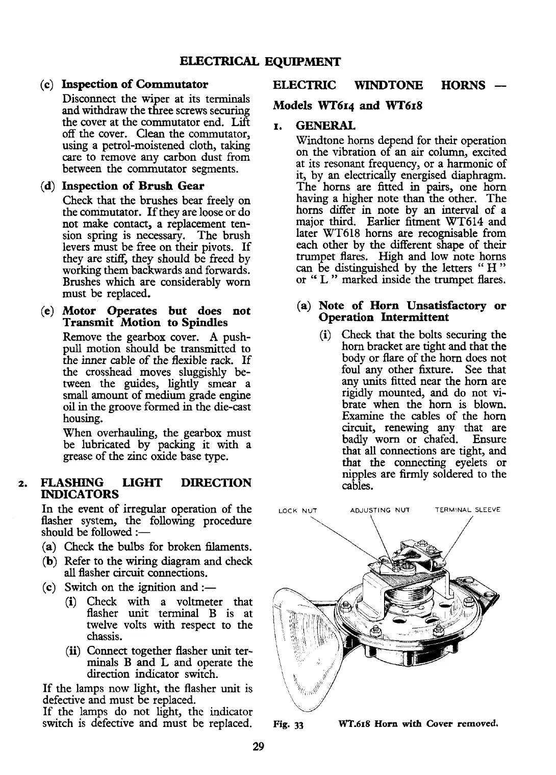
LOCK
NUT.
ADJUSTING
NUT
TERMINAL
SLEEVE
flasher system, the following procedure
should be followed
:-
(a)
Check the bulbs for broken filaments.
(b)
Refer to the wiring diagram and check
all
flasher circuit connections.
(c)
Switch on the ignition and
:-
(i)
Check with a voltmeter that
flasher unit terminal
B
is at
twelve volts with respect to the
chassis.
(ii)
Connect together flasher unit ter-
minals B and
L
and operate the
direction indicator switch.
If the lamps now light, the flasher unit is
defective and must
be
replaced.
If the lamps do not light, the indicator
switch is defective and must be replaced.
Fig.
33
wT.618
Horn
with
Cover removed.
 Loading...