7
Safety Notes
• Electrical connections to the 66540 transfer table must be
done with no electrical voltage present.
• IMPORTANT! This unit has sharp edges and points
because of the way it works.
• The 66540 transfer table is designed for use in dry areas
only.
• Analog 14 – 18 V, digital 22 V
Important Notes
• The operating instructions are a component part of the
product and must therefore be kept in a safe place as
well as included with the product, if the latter is given to
someone else.
• Please see your authorized Trix dealer for repairs or
spare parts.
• The warranty card included with this product species
the warranty conditions.
• Disposing: www.maerklin.com/en/imprint.html
• Approach tracks or tracks that are connected to another
controller must be isolated about 20 cm / 8“ from the
transfer table.
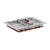
Installation
A hole measuring 20.5 x 28.5 cm / 8-1/16“ x 11-1/4“ must be cut
for the transfer table into the benchwork for your model rail-
road layout. This opening must be at least 3.8 cm / 1-1/2“ deep.
Electrical Connections for Analog Operation
In analog operation, this transfer table is controlled with the
control box included with it. Plug the 8-conductor ribbon ca-
ble from the control box into the transfer table and connect
the 4-conductor ribbon cable to a Trix transformer/switched
mode power supply unit according to the colors.
Analog Operation
The red slider switch on the control box can be pushed
upwards or downwards. This will set the direction of travel
for the transfer table. Pressing on the slider switch will start
the transfer table such that it goes only to the next track and
remains stopped there.
The two green buttons on the control box are used to supply
voltage to the left or right connection tracks respectively of
the track at which the transfer table is currently stopped.
Electrical Connections for Digital Operation with DC
Power for the Transfer Table Motor
The ribbon cable with open ends is provided for digital
operation. The control box included with the transfer table
is not used here.
The connections are done as shown on Page 14/15.
Electrical Connections for Digital Operation with AC
Power for the Transfer Table Motor
The ribbon cable with open ends is provided for digital
operation. The control box included with the transfer table
is not used here.
The connections are done as shown on Page 12/13.