9
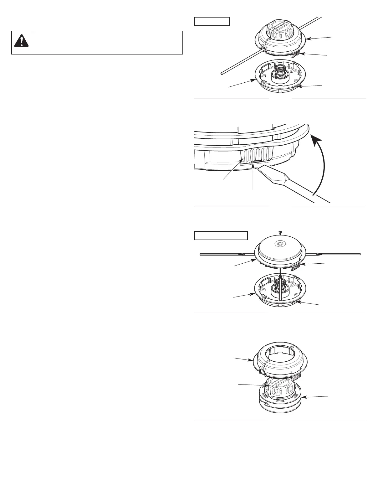
SWAPPING THE CUTTING HEADS
NOTE: The cutting head base will remain attached to the unit.
Removing the Bump Head
1. Set the unit on a flat, level surface.
2
. Disconnect the bump head from the cutting head base: Firmly
press a tab on the bump head (Fig. 6). Use your thumb. If
necessary, use a flat-head screwdriver:
a. Insert a flat-head screwdriver into the notch on the tab (Fig. 7).
b.Gently tilt the screwdriver up and hold it in place (Fig. 7).
c. While holding the screwdriver in place, gently twist the
screwdriver to unlock the tab from the tab slot (Fig. 6).
3. Remove the bump head from the cutting head base. DO NOT
disassemble or remove any other parts on the bump head or
cutting head base.
Installing the Aero-Flex® Head
1. Set the unit on a flat, level surface.
2. Install all four line blades. Refer to Replacing the Line Blades in
the Maintenance section.
3. Align the tabs on the cutting head cap with the tab slots on the
cutting head base (Fig. 8). Push the cutting head cap onto the
cutting head base until both tabs snap into place.
Removing the Aero-Flex® Head
1. Set the unit on a flat, level surface.
2. Disconnect the cutting head cap from the cutting head base:
Firmly press a tab on the cutting head cap (Fig. 8). Use your
thumb. If necessary, use a flat-head screwdriver:
a. Insert a flat-head screwdriver into the notch on the tab (Fig. 7).
b.Gently tilt the screwdriver up and hold it in place (Fig. 7).
c. While holding the screwdriver in place, gently twist the
screwdriver to unlock the tab from the tab slot (Fig. 8).
3. Remove the cutting head cap from the cutting head base. DO
NOT disassemble or remove any other parts on the cutting head
base.
Installing the Bump Head
1. Set the unit on a flat, level surface.
2. If necessary, assemble the bump head: Insert the bump knob and
inner reel into the spool cover (Fig. 9). Hold the two pieces together.
3. Align the tabs on the bump head with the tab slots on the
cutting head base (Fig. 6). Push the bump head onto the cutting
head base until both tabs snap into place.
4. If the trimming line is not loaded, load the trimming line. Refer to
Replacing the Trimming Line in the Maintenance section.
WARNING:
To avoid serious personal injury and
damage to the unit, shut the unit off before removing or
installing a cutting head.
Fig. 6
Tab
Fig. 8
Bump Head
Tab Slot
Cutting
Head Base
Tab
Tab Slot
Cutting Head
Base
Cutting Head
Cap
Aero-Flex® Head
Fig. 9
Inner Reel
Spool Cover
Bump Knob
Fig. 7
Bump Head
Tab
Notch