12
Charging process
The APC310 has an electronic reverse battery protection.
The charging current is only released if the battery is cor-
rectly connected and there is a minimum voltage of 1.2V.
The charging process is carried out in accordance with the
charging reference line with a minimum of performance loss
(see “Charging reference line”). When a temperature sensor
is used, charging is carried out on a temperature-dependent
basis.
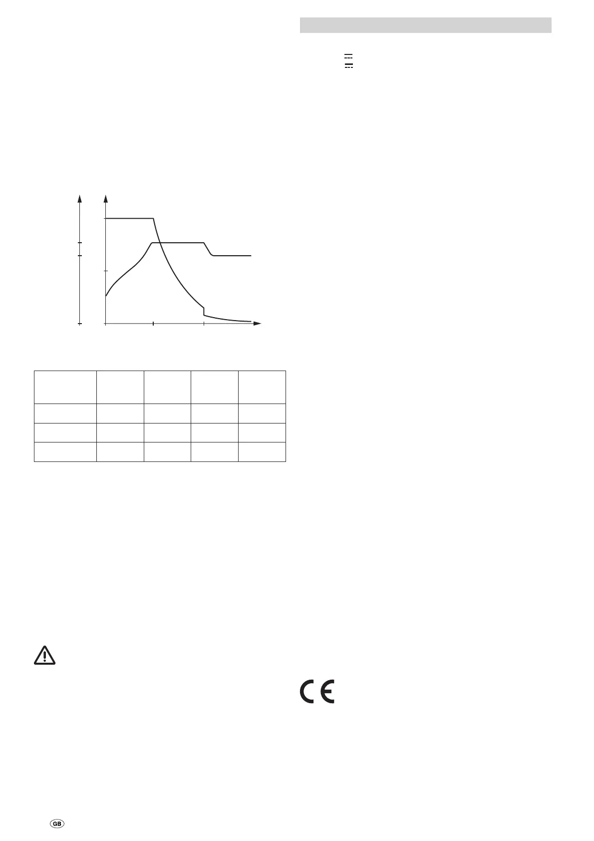
Charging reference line
HL = Main charging phase
NL = Afterloading phase
EL = Trickle charging
U
2
0
U[V]
U
1
0
50
100
I[%]
I
U
t[h]ELNLHL
Charging voltage (at 20°C)
Battery
type
HL – U
1
NL NL t[h] EL – U
2
Liquid 14,4V 14,4V 4 13,8V
Gel 14,4V 14,4V 10 13,8V
AGM 14,5V 14,5V 10 13,9V
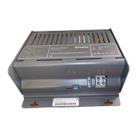
Commissioning
The device is operational as soon as it is connected to the
APS400-K and the battery.
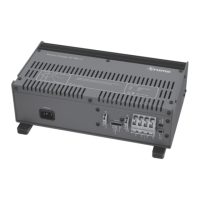
Removing the clamping space cover
Unlock the clamping space cover by pressing the two straps
at the same time and then remove (see page2, fig.A).
To attach the cover, push both straps into the slits of the hous-
ing shell and ensure that they click into place.
Maintenance
The power supply must always be completely discon-
nected before performing any maintenance work on the
device.
Clean the device and the ventilation slits with a dry and fluff-
free cloth.
Disposal
The device must be disposed of in line with the administra-
tive regulations of the respective country in which it is used.
National regulations and laws (in Germany, for example, the
End-of-life Vehicle Regulation) must be observed.
Technical data
Power supply
12V
via APS400-K
max. 22V
via solar
(System voltage: 12V,
idle voltage: panel max. 22V,
current: max. 10A,
corresponds to approx. 180Wp)
Output
Charging voltage (± 0.05V) – see “Charging reference line”
Arithmetic mean value, electronically controlled according to
the charging reference line IU
1
U
2
, sustained short-circuit pro-
tection, open-circuit protected
Nominal current
10A ± 0.5A at 35°C, above this, automatic power reduction
Residual ripple
<5%
Minimum battery voltage
1.2V
Charging process
Automatic
Temperature-dependent control (optional)
The values of the automatic switching device refer to a battery
temperature of 20 °C. If a temperature sensor is used with the
battery, these values will vary in accordance with the battery
temperature.
High temperature –> reduction of the threshold values.
Lower temperature –> higher threshold values.
Charging current lifter
max. 10A
Voltage lifter
14.5V
Monitoring under-voltage
OFF at 10.8V
ON at 12.5V
Use
To charge the batteries with 12V rated voltage and a capacity
of 50–150Ah.
Storage temperature
-20–+80°C
Housing temperature (in operation)
max. +80°C
Air humidity
5 – 95% without thawing
Noise
< 10dBA (at a distance of 1.5m)
Dimensions (L x W x H)
360 x 150 x 103mm
Weight
2.0kg
The right to effect technical modifications is reserved!