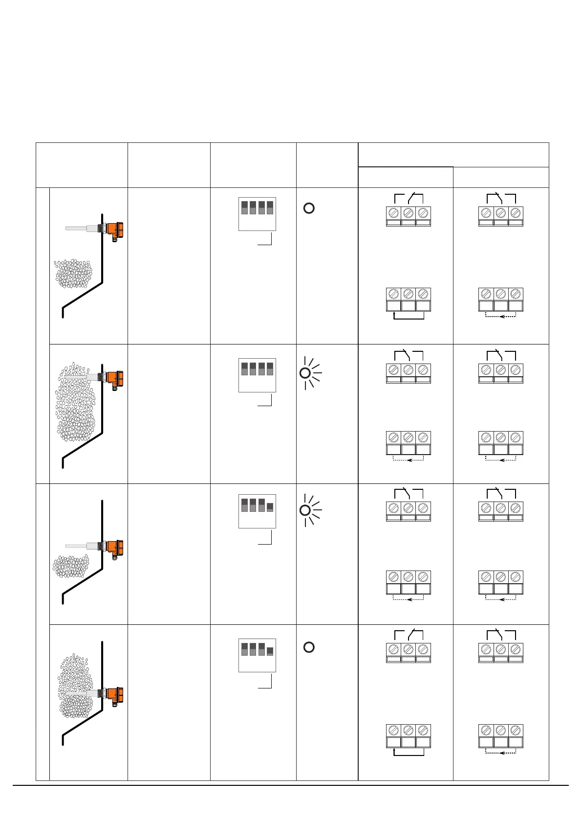
Failsafe defines that the alarm and power failure / device failure conditions are same to
the external system. Failsafe operation is best understood with the type of installation
and following matrix.
Operation Matrix - LSVR-U(S+P) (EIUSP / ERUSP)
lsvr-manual-annexure-3 www.trumen.in
Annexure-3
Page 2
Off
Off
On
On
Failsafe
Setting
Material &
Installation
Status
LED
1 2 3 4
ON
min failsafe
1 2 3 4
ON
min failsafe
Material
Status
No material
at high level.
Switch no. 4
is off, failsafe
high/maximum
Relay Contacts & PNP Output
Indicating
normal or
healthy
status.
Power ON Power OFF
1 2 3 4
ON
min failsafe
Switch no. 4
is off, failsafe
high/maximum
Material is
above the high
level or rod is
covered with
material.
Indicating
alarm
status.
No material
at low level.
Switch no. 4
is on, failsafe
low/minimum
Indicating
alarm
status.
Material is
above the low
level or rod is
covered with
material.
1 2 3 4
ON
min failsafe
Switch no. 4
is on, failsafe
low/minimum
Indicating
normal or
healthy
status.
High level / overflow detectionLow level / underflow detection
4 5 6
4 5 6
Relay ON normal
or healthy contacts.
Relay OFF alarm
contacts. (due to
power failure)
Relay OFF alarm
contacts.
Relay OFF alarm
contacts. (as it is)
I
leak
≤ 0.1mA
7 8 9
I
leak
7 8 9
I
L
I
L(max)
= 250mA
7 8 9
I
leak
I
leak
≤ 0.1mA
7 8 9
I
leak
I
leak
≤ 0.1mA
7 8 9
I
leak
I
leak
≤ 0.1mA
7 8 9
I
leak
I
leak
≤ 0.1mA
4 5 64 5 6
Relay OFF alarm
contacts.
Relay OFF alarm
contacts. (as it is)
4 5 64 5 6
4 5 6
4 5 6
Relay ON normal
or healthy contacts.
Relay OFF alarm
contacts. (due to
power failure)
I
leak
≤ 0.1mA
7 8 9
I
leak
7 8 9
I
L
I
L(max)
= 250mA


 To Next Page