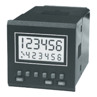
5
Relays (see page 38)
The P1 and P2 relays can be programmed independently to be normally-open or
normally-closed. The contacts of a normally-closed relay will open when it operates, and
those of a normally-open relay will close.
The relays can be programmed independently to operate in pulsed or latched mode. In
pulsed mode (P1 relay:
Auto Reset Off
only) the relay will operate for a length of time set
by the program. In latched mode the relay will operate, and stay in that condition until
reset.
The relays can be programmed to revert to a known safe state in the event of a power
failure or on entering program mode. The three alternatives are:
Current
- the contacts will remain in the same state as before the event;
Reset
- the contacts will revert to their normal, unoperated state;
Set
- the contacts will revert to their operated state.
Count Direction (see page 36)
In all modes, count direction is dependent on Reset mode (see
Programming
) and
Sink/Source wiring, as shown in the diagrams. The count direction and the edges that
trigger the count are shown by the arrows.
For unidirectional mode, the count directions obtained with input B open-circuit are
marked *.
Note:
The count direction must not change in less than 25 µs, or the unit may not operate
correctly.
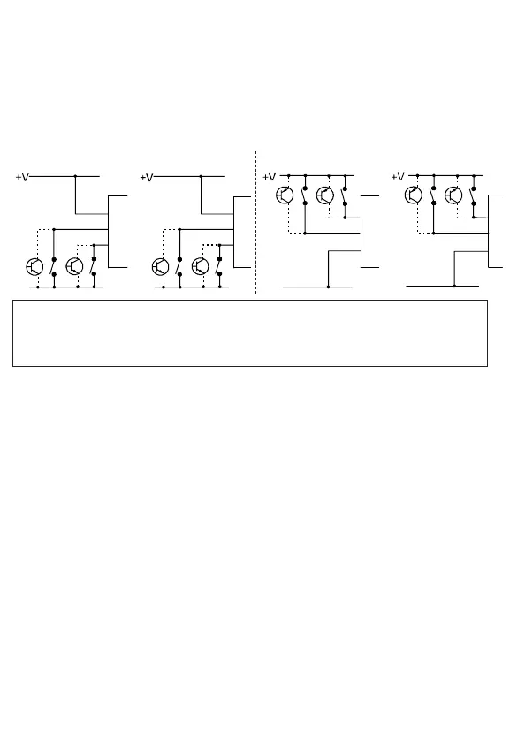
Sink Inputs (NPN)
Source Inputs (PNP)
Input Polarity (see page 37)
The opto-isolated inputs A and B (pins 8 and 9) can be sink or source dc inputs,
depending on the way they are wired, with respect to their Common input (pin 10), as
shown in the examples below, and on pages 37 and 38.
The opto-isolated inputs K and R (pins 12 and 13) can be sink or source ac or dc inputs,
depending on the way they are wired, with respect to their Common input (pin 14), as
shown in the examples below and on pages 37 and 38.
These two sets of inputs are completely isolated from each other, and also from the
supply pins.
Note: Common Pins 10 and 14
These pins must always be correctly connected for their inputs to work.
For dc signals, to +V or -V, as shown in the examples above and on page 37.
For ac signals (12/13/14 only), as shown in example
4
on page 37.