Do you have a question about the Trumpf TruLight 1000 and is the answer not in the manual?
Lists the different versions of the TruLight 1000 lighting system covered.
Provides contact information for the manufacturer and distributor.
Outlines copyright and property rights for the manual.
Discusses product development and manual updates.
Lists registered trademarks.
Details on device identification via labels and serial numbers.
Information on manual identification and version status.
Instructions for checking delivery and handling transportation damage.
Explains how to identify system components using serial numbers.
Lists the necessary tools and equipment for installation.
Specifies the required qualifications for personnel performing installation.
Details environmental conditions for device operation and storage.
States compliance with CE and UL markings and directives.
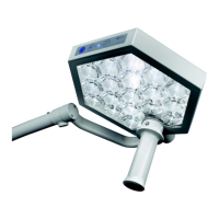
Defines the intended use and working range of the lighting unit.
Highlights key features like high light intensity and heat generation.
Lists conditions and environments where the device should not be used.
Outlines conditions for product warranty and liability.
Requirements for installation documentation and handover.
Guidelines for proper disposal of the device.
Procedures for structural engineer approval of mounting points.
Recommendations for fasteners and mounting techniques for different ceiling/wall types.
Requirements for electrical connections by specialized companies.
Explains how safety information is presented using signal words and symbols.
Details various safety symbols used throughout the manual.
Explains symbols found on the device itself.
Summarizes key safety warnings including gas explosion, magnetic fields, and electric shock risks.
Specifies the maximum load limits for the support arm system.
Warns about risks associated with light head swivel movement.
Safety precautions for cleaning and disinfecting the device.
Procedures for initial commissioning and handover of the system.
Guidance on identifying system units and consulting support if needed.
Explains the use of serial numbers and device labels for identification.
Details markings on the ceiling-mounted version.
Details markings on the wall-mounted version.
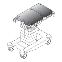
Details markings on the mobile stand version.
Introduces the three assemblies for the central axis installation.
Describes the assembly of the central axis in three variants.
Lists available lengths for ceiling pipes.
Details the pre-assembled support arm system components.
Details the partially pre-assembled light unit components.
Information on the on-site power supply for the ceiling version.
Instructions for attaching the ceiling anchor plate to the slab ceiling.
Step-by-step guide for attaching the anchor plate with heavy-duty anchors.
Instructions for installing the flange plate on the anchor plate using threaded rods.
Detailed steps for flange plate installation with threaded rods.
Steps for flange plate installation using hexagonal profiles.
Instructions for direct installation of flange plate on slab ceiling.
Steps for attaching the flange plate with heavy-duty anchors.
Instructions for connecting the on-site power supply.
Guidance on mounting the canopy.
Instructions for installing the support arm system on the central axis.
Steps to prepare for the support arm system assembly.
Procedure for dismantling the circlip for the support arm system.
Steps for mounting the circlip for the support arm system.
Methods to check the correct installation of the circlip.
Acoustic method to verify circlip fit.
Visual checks for correct circlip mounting.
Mechanical test to verify circlip installation.
Final steps to complete the support arm system installation.
Instructions for installing the light unit onto the support arm system.
Procedures for checking and controlling the system's movements.
Method to check the horizontal levelling of the lighting system.
Details the rotation and swivel ranges of the support arm system.
Details the rotation and swivel ranges of the light head.
Introduces the three assemblies for the wall bearing installation.
Describes the components of the wall bearing assembly.
Describes the pre-assembled support arm system.
Describes the partially pre-assembled light unit.
Information on the power supply for the wall-mounted version.
Instructions for fastening the wall bearing to the wall.
Notes on wall stability, especially for lightweight construction.
Steps to remove the casing of the wall bearing.
Steps for attaching heavy-duty anchors for the wall bearing.
Instructions for connecting the on-site power supply.
Steps for mounting and connecting the power supply box.
Details on connecting the power supply box to the wall bearing.
Procedures for connecting via the mains cable.
Instructions for installing the support arm system on the wall bearing.
Steps to prepare for the support arm system assembly.
Procedure for dismantling the circlip for the support arm system.
Steps for mounting the circlip for the support arm system.
Methods to check the correct installation of the circlip.
Acoustic method to verify circlip fit.
Visual checks for correct circlip mounting.
Mechanical test to verify circlip installation.
Final steps to complete the support arm system installation.
Instructions for installing the light unit onto the support arm system.
Procedures for checking and controlling the system's movements.
Method to check the horizontal levelling of the lighting system.
Details the rotation and swivel ranges of the support arm system.
Details the rotation and swivel ranges of the light head.
Introduces the four assemblies for the mobile stand version.
Lists components of the stand base assembly.
Describes the pre-assembled stand pipe unit.
Describes the spring arm assembly.
Lists components of the light unit assembly.
Information on establishing power supply for the mobile stand version.
Instructions for assembling the stand base, including lockable castors.
Steps for assembling the stand rod and attaching the power supply unit.
Instructions for assembling the spring arm onto the stand rod.
Steps to prepare for spring arm assembly.
Procedure for dismantling the circlip for the spring arm.
Steps for mounting the circlip for the spring arm.
Methods to check the correct installation of the circlip.
Acoustic method to verify circlip fit.
Visual checks for correct circlip mounting.
Mechanical test to verify circlip installation.
Final steps to complete the spring arm installation.
Instructions for installing the light unit onto the spring arm.
Procedures for checking and controlling the system's movements.
Details the rotation and swivel ranges of the spring arm.
Details the rotation and swivel ranges of the light head.
Steps for performing a functional test and visual inspection of the system.
Specifies when a repeat test is required after component replacement.
Warnings about contamination risks from loose or damaged parts.
Risks and precautions regarding electric shock.
Procedures for safely decommissioning a faulty or end-of-life system.
Procedures for handing over the system to the operator.
Steps to adjust the spring force for proper arm movement.
Steps to adjust the braking force for stable light head positioning.
Procedure for replacing the fuse in the mobile stand version.
Lists high-wear parts like handles and brake screws.
Electrical specifications and operating data for the device.
Performance data for the lighting system, including intensity and color.
Physical dimensions and weight of the light head.
Guidelines and declarations regarding electromagnetic compatibility.
Details immunity tests and electromagnetic environment guidelines.
Guidelines for immunity to interference from radio devices.
Lists immunity levels for RF fields from wireless communication devices.
Recommended separation distances for RF devices.
Lists the additional documents included in the attachment.
Circuit diagram for the ceiling version.
Circuit diagram for the mobile version.
Circuit diagram for the wall version.
Drawing of the switch cabinet.
Borehole template for ceiling components.
Borehole template for wall bearing.
| Brand | Trumpf |
|---|---|
| Model | TruLight 1000 |
| Category | Medical Equipment |
| Language | English |