Do you have a question about the TTP Ventus General Purpose Disc Pump Drive PCB and is the answer not in the manual?
The TTP Ventus General Purpose Disc Pump Drive PCB is a versatile electronic board designed to control TTP Ventus Disc Pumps. It serves as a core component for integrating these pumps into various systems, offering both open-loop and closed-loop control capabilities. The PCB is provided in a "bare" format, intended for skilled and trained personnel to integrate it into test fixtures, prototypes, and product assemblies.
The primary function of the Drive PCB is to power and control TTP Ventus Disc Pumps, which utilize a multi-award-winning technology based on non-linear acoustics. These pumps generate a high-frequency acoustic standing wave within a specially designed acoustic cavity, causing the actuator to drive the cavity in and out, creating a standing pressure wave. This results in a net volume change of the cavity during operation, leading to pumping action. The Drive PCB manages the complex high-frequency operation of the Disc Pump, ensuring precise control over its performance.
The PCB supports various control interfaces, making it adaptable to different application requirements. For basic use cases, a three-wire connection (power supply, ground, and analog control) is sufficient. For more sophisticated applications, the Drive PCB can be controlled via a TTL-level serial UART link. This digital interface allows for comprehensive configuration and control of the pump's operation.
A key feature of the Drive PCB is its ability to implement closed-loop control. This means it can regulate parameters such as pressure, vacuum, or flow by receiving feedback from external sensors. Customers can provide 0-3.3 V analog signals from sensors (e.g., pressure or flow sensors) to the PCB's analog inputs. The PCB then processes these signals to adjust the pump's operation, maintaining the desired setpoint. This closed-loop functionality enhances the precision and stability of the pump's performance in demanding applications.
The PCB also acts as an I2C master, enabling communication with a selection of digital sensors relevant to common Disc Pump applications. This master capability allows the Drive PCB to gather data from various peripheral devices, further enhancing its ability to perform sophisticated control tasks. It's important to note that the PCB does not support I2C control by another master device; its I2C functionality is solely for controlling peripheral devices.
The Drive PCB is designed for ease of integration and flexible control. It requires a 3.5-5.5V power supply, which is a common voltage range in many electronic systems. The board includes a 3V3 voltage regulator, providing a stable 3.3V supply for internal components and potentially for external low-power devices.
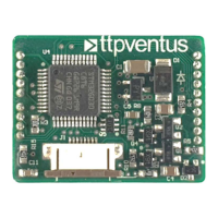
Interfacing with the Disc Pump is done via an 8-way 0.5mm pitch FFC (flat flex connector). Proper seating of the pump's "Flexi Tail" into this connector is crucial for reliable operation. The manual provides clear instructions on how to correctly connect the Flexi Tail, including ensuring the connector is fully open, sliding the Flexi Tail in until a hard stop is reached, and then closing the connector by applying even pressure. A visual inspection is recommended to ensure approximately 5mm of the Flexi Tail is exposed, confirming proper seating.
The PCB offers multiple analog inputs (pins 7-9) that can be configured for various control purposes. A single analog input can be used for open-loop control of pump drive power, where the pump's output is directly proportional to the input voltage. Alternatively, multiple analog inputs can be used together for closed-loop control, with one input measuring a sensor output (e.g., pressure) and another receiving a target setpoint. This flexibility allows users to implement custom control strategies tailored to their specific application needs.
Digital control is facilitated through a TTL-level serial UART interface (pins 14 and 15). This interface allows for comprehensive configuration and control of the PCB without relying on analog inputs. Users can send commands and receive data, enabling advanced control modes and parameter adjustments. Additionally, GPIO A and D pins (pins 16 and 10, respectively) can be used to toggle the pump ON/OFF. These pins have internal pull-ups, meaning they can be left floating if not actively driven, simplifying their use.
For initial setup and configuration, the TTP Ventus Pump Control App can be used in conjunction with a TTP Ventus Motherboard PCB. This app provides a user-friendly interface to set control modes and associated parameters. Configuration settings can be saved directly to the Drive PCB, allowing it to operate autonomously on power-up without requiring continuous connection to the app. This feature is particularly useful for production environments, where the app can be used as a one-time configuration tool before installing the Drive PCB into the final system.
The Drive PCB is designed for robust operation, but proper handling and integration are essential for its longevity and performance. As a "bare" PCB, it requires careful handling to prevent damage from electrostatic discharge (ESD). Users should remove the Drive PCB from its protective ESD bag only when ready for integration and follow standard ESD precautions.
During integration, users must take care not to create short circuits between exposed conductive parts of the PCB. Short circuits can lead to malfunctioning and heating, potentially damaging the board. The manual provides indicative electrical data, including AC and DC voltages on the PCB, to help users assess safety and prevent such issues. The AC voltage on the PCB can reach up to 120 Vpp (at 20-22 kHz), and the DC voltage can be up to 60 V max. These values highlight the importance of careful handling and proper insulation during integration.
The Disc Pumps, when in operation, emit ultrasound. While the sound pressure level at maximum power (1.4W) at a distance of 30cm is typically 70-80 dB SPL (at 20-22 kHz), which is equivalent to less than 10 phon, users should be aware of this characteristic.
For ongoing support and troubleshooting, TTP Ventus provides resources on its website, including technical information, FAQs, and application notes. This documentation helps users understand the device's operation, troubleshoot common issues, and optimize its performance in various applications. For more specific technical assistance, direct contact with TTP Ventus support is available.
The Drive PCB's design, with its various input/output options and software configurability, allows for updates and modifications to its firmware. This means that future enhancements or custom functionalities can be loaded onto the onboard microcontroller using pins 12 and 13 (SWD IO and SWD CLK), which are used for software debug and firmware loading. This capability ensures that the PCB can adapt to evolving requirements and benefit from future improvements.
| Max Current | 2A |
|---|---|
| PWM Frequency | 20 kHz |
| Dimensions | 60mm x 40mm x 15mm |
| Protection | Overcurrent |
| Storage Temperature | -20°C to +70°C |