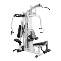
IG. 1 On a flat surface, lay the Base Frame (#2) down
nd insert two Plastic Insert Caps 2” Sq. (#64). Next, insert two
lastic Insert Caps 2” Sq. w/groove (#63) onto the front
tabilizer of the Base Fr ame (#2), as shown above.
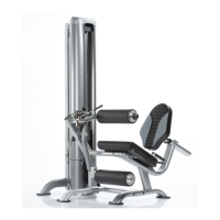
FIG. 2 Locate the Low Row Foot Support (#37) and slid
a Hard Grip .875 X 8 (#60) over each end of the tube, as
illustrated above. The hard Grip .875 X 8 (#60) fits very tightl
onto the Low Row Foot Support (#37) and it may be
necessary to use windex or a household glass cleaner (as
shown) to complete this procedure. Next, insert one Plasti
Insert Cap 2” Sq. (#64) into the tube-end of the Low Row Foo
Support (#37).
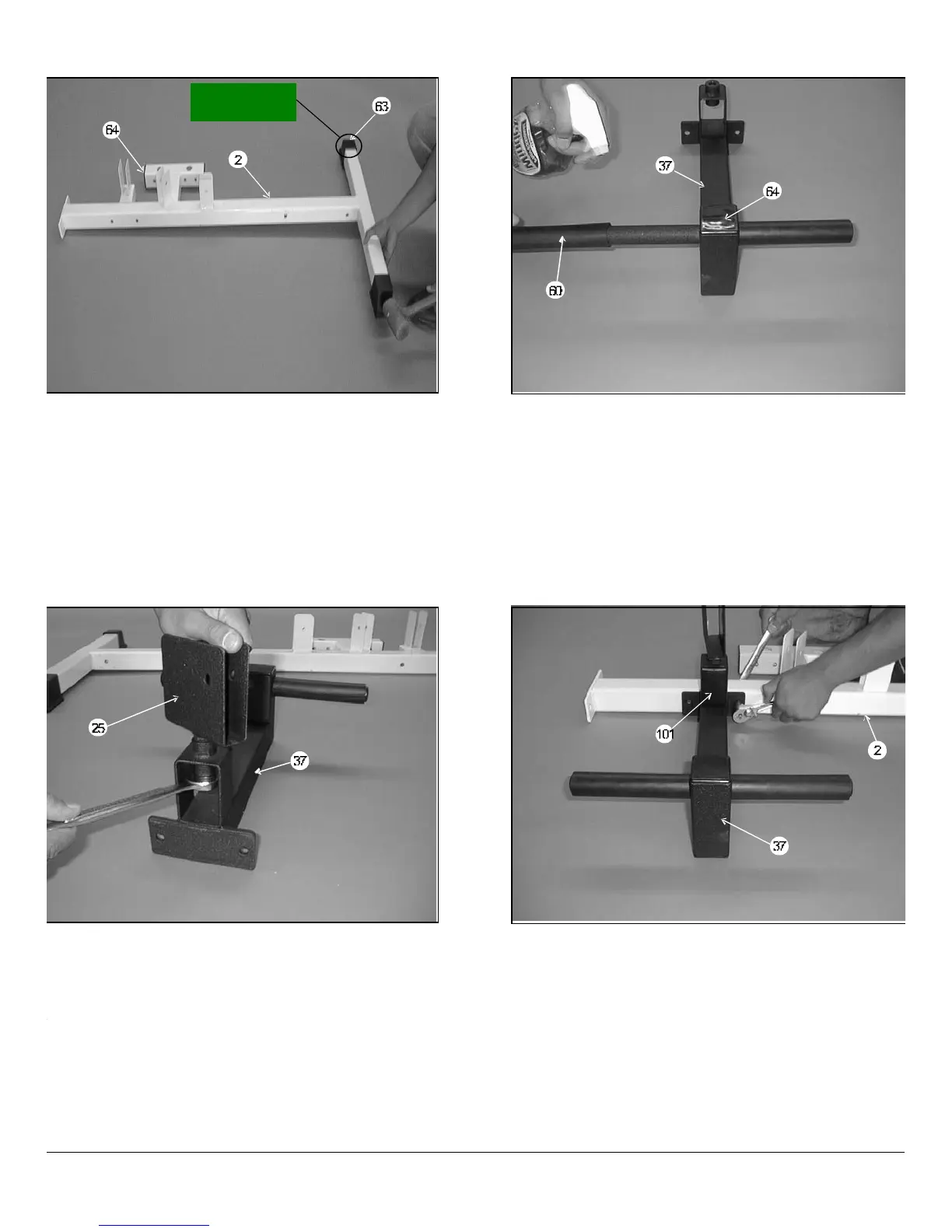
IG. 3 Install the Low Row Swivel Pulley Bracket (#25)
nto the receptacle on the Low Row Foot Support (#37) and
ecure it using one Nylon Insert Jam Lock Nut 1/2-13 (#88)
nd one Flat Washer SAE 1/2 (#89). Note: It is recommended
hat the axle on the Low Row Swivel Pulley Bracket (#25)be
ubricated with grease prior to this assembly.
FIG. 4 Attach the Low Row Foot Support (#37) to the
Base Frame (#2) and secure it using using two Hex Head Cap
Screws 3/8-16 X 2 3/4 (#77), four Flat Washers SAE 3/8 (#90)
and two Nylon Insert Jam Lock Nuts 3/8-16 (#86). Next, insert
two Plastic Insert Caps 2 X 3 (#101) into the pulley bracket
housing on the Low Row Foot Support (#37).
Owners’ Manual: Assembly Instruction
IMPROVED
See #63 on page 19
SL-IV Muscle IV Home Gym
2
 Loading...