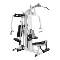
IG. 5 Attach the Rear Upright (#4) to the Base Frame (#2)
nd secure it using two Hex Head Cap Screws 3/8-16 X 2 3/4
#77), four Flat Washers SAE 3/8 (#90) and two Nylon Insert
ock Nuts 3/8-16 (#86). Note: Do not tighten this hardware
ssembly at this time. Next, insert two Plastic End Caps 2” Sq.
/groove (#63) into the Rear Upright (#4), as shown above.
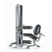
FIG. 6 Attach the Front Upright (#3) to the Base Frame
(#2) and secure it using one Hex Head Cap Screw 3/8-16 X 2
3/4 (#77), two Flat Washers SAE 3/8 (#90) and one Nylon
Insert Jam Lock Nut 3/8-16 (#86). Note: Do not tighten this
hardware assembly at this time.
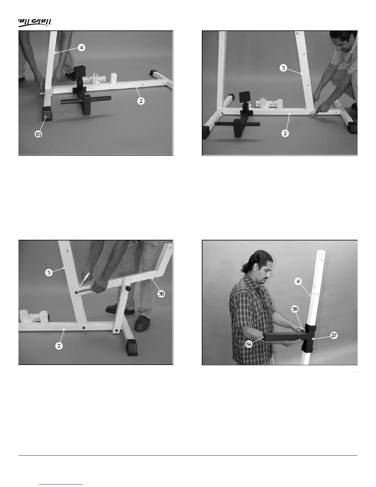
IG. 7 Attach the Leg Extension Seat Frame (#38) to the
ase Frame (#2). Secure the Leg Extension Seat Frame
#38) to the Base Frame (#2) using one Hex Head Cap Screw
/8-16 X 4 1/2 (#93), two Flat Washers SAE 3/8 (#90) and one
ylon Insert Jam Lock Nut 3/8-16 (#86). Next, secure the Leg
xtension Seat Frame (#38) to the Front Upright (#3) using
ne Hex Head Cap Screw 3/8-16 X 2 3/4 (#77), two Flat
ashers SAE (#90) and one Nylon Insert Jam Lock Nut 3/8-16
#86). Note: Do not tighten this hardware assembly at this
ime.
FIG. 8 Slide the Pec Dec Adj Seat Tube (#27) onto th
Rear Upright (#4),as shown above. Note: Position the Pe
Dec Adj Seat Tube (#27) with the Push-Pull Pin 1/2 (#56
facing the same side as the selector holes on the Rear Uprig
(#4).
MSL-IV Muscle IV Home Gym
3
 Loading...