TG-11L Leg Press (Option)
2
Owners’ Manual: Assembly Instructions
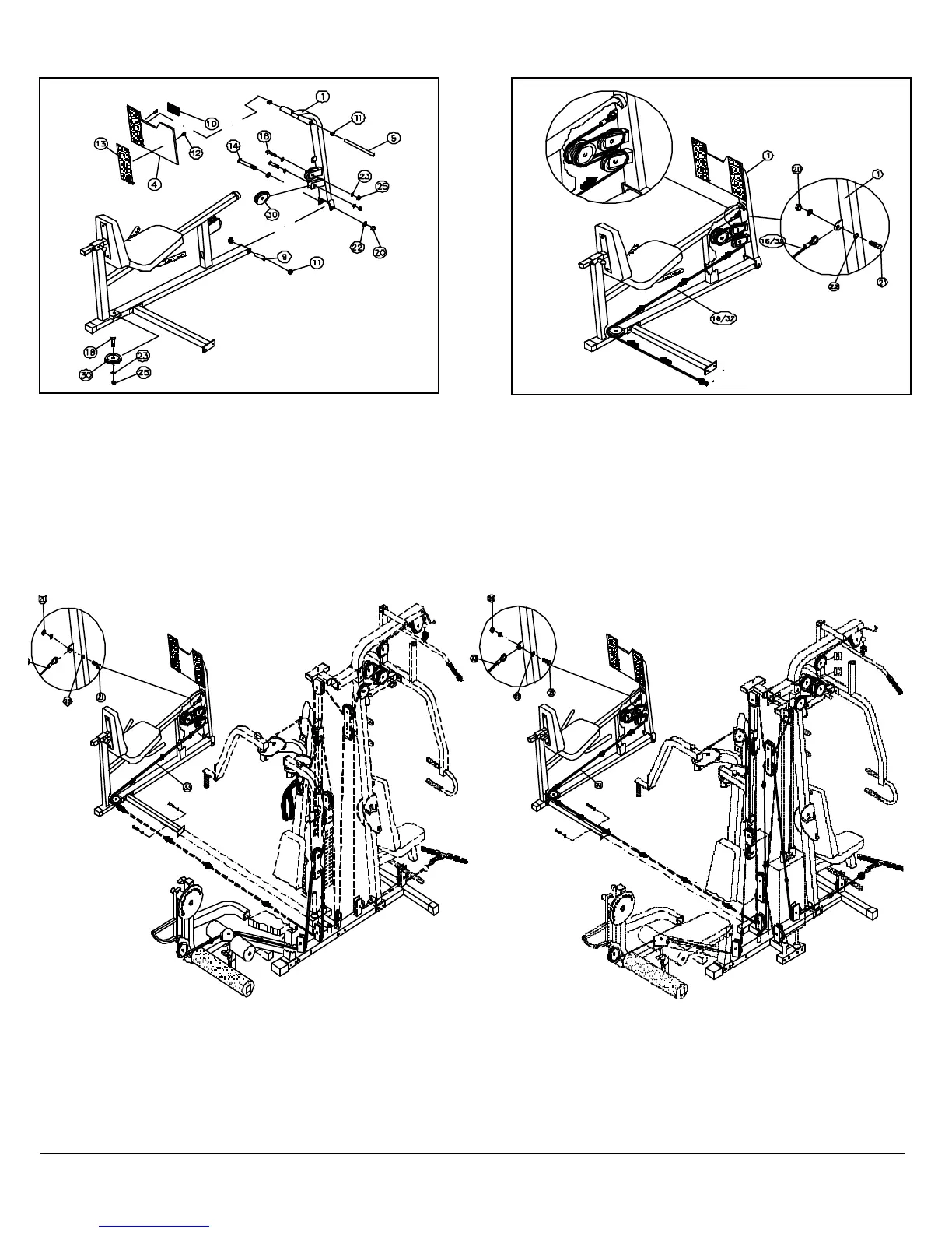
FIG. A Attach the TG-11L to the TG-150, as shown above, and
secure it into using two Hex Head Cap Screws 3/8-16 X 3 3/4 (#15), four
Flat Washers SAE 3/8 (#23) and two Nylon Insert Jam Lock Nuts 3/8-16
(#25). When installing the TG-11L you will receive a new cable, the Main
Cable (#16-Labeled with tape TG-150). This Main Cable (#16-Labeled
with tape TG-150) will replace the existing cable you are using for the
Leg Extension station on the TG-150. This new Main Cable (#16-Labeled
with tape TG-150) will now be used for the Leg Extension and the Leg
FIG. 2 Attach three Nylon Pulleys 4 1/2 Rd. (#30) ,as shown above.
Attach two of the Nylon Pulleys 4 1/2 Rd. (#30) to the brackets located
on the Fulcrum (#1) and then one on the Main Frame (#2). Secure all
Nylon Pulleys 4 1/2 Rd. (#30) into place using three Hex Head Cap
Screws 3/8-16 X 1 3/4 (#18), six Flat Washers SAE 3/8 (#23) and three
Nylon Insert Jam Lock Nuts 3/8-16 (#25). Next, insert the Small Axle
(#9) into the Main Frame (#2). Then mount the Fulcrum (#1) onto the
front of the Main Frame (#2) and secure it into place using one Hex
Head Cap Screw 1/2-13 X 5 1/2 (#14), two Flat Washers SAE 1/2 (#22)
and one Nylon Insert Jam Lock Nut 1/2-13 (#20) . Next, insert the Foot
Plate (#4) onto the Fulcrum (#1), as shown above, with the Large Axle
(#5) and secure it into place using two Set Screws 3/8-16 X 1/2 (#12).
Note: It is recommended to lubricate the axles using a multi-purpose
Fig. 3 Note: Before routing the cable, locate the Main Cable (#16-
Labeled with tape TG-150) or the Main Cable (#31-Labeled with
tape TG-250). The label on the cable will determine which cable is
needed for either the TG-150 or the TG-250. Route the Main Cable
(#31 or #16), as illustrated above, beginning at the TG-150 or TG-250
and finishing at the Fulcrum (#1) mounting bracket. Secure the Main
Cable (#31 or #16) to the Fulcrum (#1) mounting bracket using one
Hex Head Cap Screw 1/2-13 X 1 (#21), two Flat Washers SAE 1/2
(#22) and one Nylon Insert Jam Lock Nut 1/2-13 (#20). Note: Use Fig.
A and Fig. B and your TG-150 Or TG-250 Instruction Manual for
further clarification of the this cable routing.
FIG. B Attach the TG-11L to the TG-
secure it into place using two Hex Head Cap Screws 3/8-
four Flat Washers SAE 3/8 (#23) and two Nylon Insert Jam Lock Nuts 3/8
16 (#25). When installing the TG-11L you will receive a new cable,
Cable (#31-Labeled with tape TG-250). This Main Cable (#31-
with tape TG-250)
will replace the existing cable you are using for the
Low Row station on the TG-250. This new Main Cable (#31-
tape TG-250)
will now be used for the Low Row and the Leg Press
Note: Some Parts Not
Shown or cut away for
clarity
Fig. B
TG-11L to TG-250
Cable Routing Diagram
Fig. A
TG-11L to TG-150
Cable Routing Diagram
 Loading...