Do you have a question about the Turbo Air M3F47-2 and is the answer not in the manual?
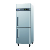
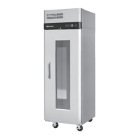
Details front view and plan view components for 1-door models.
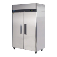
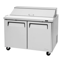
Details front view and plan view components for 2-door models.
Details front view and plan view components for 3-door models.
Wiring diagram for the M3R24-1 model.
Wiring diagram for the M3R24-2 model.
Wiring diagram for the M3F24-1 model.
Wiring diagram for the M3F24-2 model.
Wiring diagram for M3R47-2 and M3R47-4 models.
Wiring diagram for M3F47-2 and M3F47-4 models.
Wiring diagram for M3R72-3 and M3R72-6 models.
Wiring diagram for M3F72-3 and M3F72-6 models.
Details of the top grille and display PCB.
Details of the refrigeration compartment components.
Details of the drain pan assembly and its components.
Details of the drain case assembly.
Details of the condenser fan motor assembly.
Details of the control box components.
Details of the door and its gasket.
Details of cooling compartment ducts for specific models.
Details of freezer evaporator and fan for specific models.
Details of freezer/refrigerator ducts for specific models.
Details of freezer evaporator and fan for specific models.
Specifications and models for compressors.
Specifications for compressor relays.
Specifications for condenser dryers.
Specifications for capacitors.
Specifications for evaporator fan motors.
Specifications for condenser fan motors.
Specifications for evaporator defrost heaters.
Specifications for lamp bulbs.
Specifications for transformers.
Specifications for main PCBs.
Operating instructions for the refrigerator's electronic controller.
How to adjust temperature settings using control buttons.
Understanding the internal temperature readings on the display.
How the evaporator fan motor is activated.
Operating instructions for the freezer's electronic controller.
Steps for initiating a manual defrost cycle.
Information on factory defrost cycle intervals.
Steps for disassembling and replacing the top grille.
Instructions for replacing doors on single-door models.
Detailed steps for replacing doors on specific single-door models.
Instructions for replacing doors on double-door models.
Detailed steps for replacing doors on specific double-door models.
Lists components within the refrigeration compartment.
Steps to disassemble the duct and replace the lamp.
Steps to replace temperature and defrost sensors.
Steps to replace the evaporator coil and F-sensor.
Steps to replace the defrost heater in freezer units.
Steps to replace the evaporator fan motor and blade.
Lists components within the control box.
Lists components of the condenser unit.
Steps to disassemble liner frame covers for heaters.
| Number of Doors | 2 |
|---|---|
| Capacity | 47 cubic feet |
| Exterior Material | Stainless Steel |
| Interior Material | Aluminum |
| Defrost Type | Automatic |
| Width | 51.75 inches |
| Energy Efficiency | ENERGY STAR Qualified |
| Refrigerant | R290 |
| Voltage | 115 Volts |