Connecting HF Read/Write Heads for HF Bus Mode
8
Hans Turck GmbH & Co. KG | T +49 208 4952-0 | F +49 208 4952-264 | more@turck.com | www.turck.com
3
Connecting R
ead/Write Heads for the HF Bus Mode
The maximum permissible length of the bus is 50 m.
The following accessories are required for the bus mode:
n The VT2-FKM5-FKM5-FSM5 (Ident-No. 6930573) junction boxes are required for connecting
several read/write heads to an RFID port
n RSE57-TR2/RFID bus terminating resistor (Ident-No. 6934908)
n Optional: VB2-FKM5-FSM5.205-FSM5.305/S2550 junction box (Ident-No. 6936821) for feed-
ing in an additional power supply
n RFID connection cables (e.g. RK4.5T-0.3-RS4.5T/S2503)
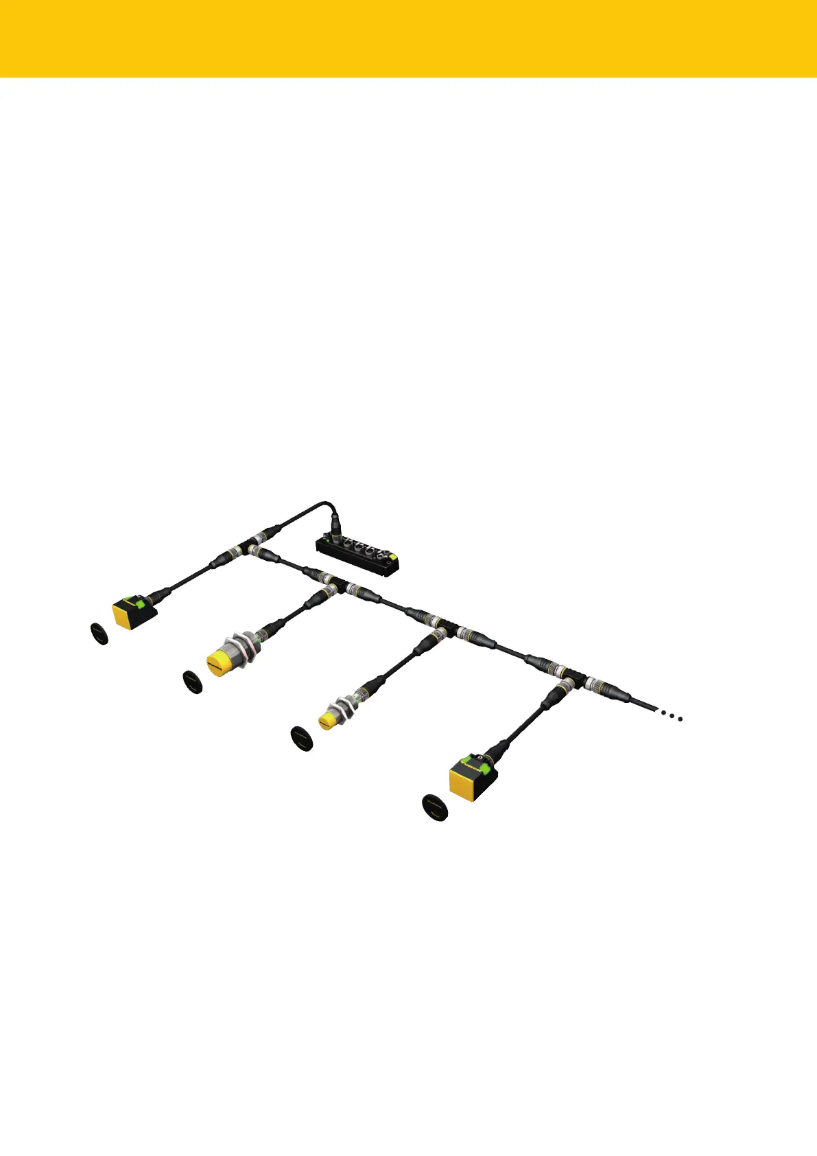
Connect the read/write head as per the figure below. The maximum length of the spur
line is 2 m.
Take the power supply into account, particularly at switch-on (see data sheet), as well as
the maximum current carrying capacity of the lines (4 A).
Take the voltage drop on the line into account. If necessary provide an additional power
supply between the read/write heads using junction box VB2-FKM5-FSM5.205-FSM5.305/
S2550.
Connect a terminating resistor (e.g. RSE57-TR2/RFID) behind the last read/write head.
TBEN-S2-2RFID-4DXP
VT2-FKM5-FKM5-FSM5
RFID connection cable
(e.g. RK4.5T-0.3-RS4.5T/S2503)
TN-M18-H1147/C53
TN-CK40-H1147/C53
TN-M30-H1147/C53
up to 32 per port
Fig.2: HF bus mode setup
 Loading...