EasyManua.ls Logo

Turing TF-AMS5AV2E - User Manual

Turing TF-AMS5AV2E
5 pages
Print Icon
To Next Page IconTo Next Page
Loading...
TF-AMS5AV2E Multisensor IP Camera Quick Installation Guide
Accessories
Rubber Kit Quick Installation
GUide
Mounting
Accessory Kit &
Desiccant
Camera Cable
1
2
3
1
Power (24VAC,60VA /24VDC,30W)
2 Alarm
3 Audio (2 cables)
Dimensions
247.5mm
202.3mm
142.3mm
Wall Mount Bracket Assembly
1. Loosen the 6 anti-drop screws on the top
cover and open it.
2. Remove and discard the protective EPE from
the lens modules.
(EPE)
3. Add a desiccant to the recommended
position as below.
DESICCANT
NPT PLUG
4. Plug the spring cable back to the top cover.
Then lock the 6 anti-drop screws on the top
cover.
5. Loosen the anti-drop screw on the lateral side
of the bottom cover.
6. Rotate the cap (
) from LOCK to OPEN in
order to remove the cap.
7. Loosen the 3 anti-drop screws on the bottom
plate and open it.
8. Prepare the network cable and wire it through
the grommet on the bottom plate.
9. Place the bottom plate back to the camera and
lock the 3 anti-drop screws to secure it.
10. Align the bottom cap to the bracket handle
and rotate it until it is fixed on the wall mount
bracket.
11. Fasten the safety wire on the hook.
12. Rotate the camera from OPEN to LOCK in
order to fix the camera. The
mark should
be aligned with the LOCK (□) mark.
13. Lock the anti-drop screw on the lateral side
of the bottom cover to fix the camera.
Question and Answer IconNeed help?

Do you have a question about the Turing TF-AMS5AV2E and is the answer not in the manual?

Overview

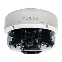
The TF-AMS5AV2E is a multisensor IP camera designed for comprehensive surveillance, offering various viewing angles and flexible installation options. It is intended for use with a Turing NVR and integration with the Turing Vision platform.

Function Description:

The TF-AMS5AV2E is an advanced IP camera capable of providing multiple simultaneous video streams from its various sensors, allowing for wide-area coverage with a single device. It supports different lens positions for 180°, 270°, and 360° views, which can be manually adjusted to suit specific surveillance needs. The camera integrates with Turing Smart Utility for setup and configuration, and it can be added to an NVR as multiple separate channels, one for each sensor. It also supports integration with the Turing Vision platform for cloud-based management and monitoring.

Important Technical Specifications:

  • Power: 24VAC, 60VA / 24VDC, 30W.
  • Connectivity: Network cable (NPT Plug).
  • Default IP Address: 192.168.1.168 (if no DHCP server is present).
  • Default Credentials: Username: admin, Password: 123456.
  • Protocol: ONVIF (for NVR connection).
  • Total Camera Number (for NVR): 4 (each multisensor camera populates 4 NVR channels).
  • Lens Views: Supports 180° Wide, 270° Corner, 360° views, 270° Wide, and 180° Tele configurations.
  • Field of View (FOV) and Tilt:
    • 180° Wide: FOV: 100° (top), 90° (sides); Tilt: 90° (top), 35° (sides).
    • 270° Corner: FOV: 100° (top), 90° (sides); Tilt: 90° (top), 35° (sides).
    • 360°: FOV: 100° (top), 90° (sides); Tilt: 90° (top), 35° (sides).
    • 270° Wide: FOV: 70° (all sensors); Tilt: 35° (all sensors).
    • 180° Tele: FOV: 100° (top), 70° (sides); Tilt: 90° (top), 35° (sides).
  • Dimensions: 247.5mm (diameter) x 202.3mm (height) / 142.3mm (base height).
  • Power over Ethernet (PoE): Requires IEEE802.3af compliant at 15.4W. For full functionality, it delivers at least 30W.

Usage Features:

Installation:

The camera offers versatile mounting options including wall mount, pendant mount, and ceiling mount.

  • Wall Mount Bracket Assembly:

    1. Loosen 6 anti-drop screws on the top cover and open it.
    2. Remove and discard protective EPE from lens modules.
    3. Add a desiccant to the recommended position.
    4. Plug the spring cable back to the top cover and lock the 6 anti-drop screws.
    5. Loosen the anti-drop screw on the lateral side of the bottom cover.
    6. Rotate the cap from LOCK to OPEN to remove it.
    7. Loosen 3 anti-drop screws on the bottom plate and open it.
    8. Prepare the network cable and wire it through the grommet on the bottom plate.
    9. Place the bottom plate back to the camera and lock the 3 anti-drop screws.
    10. Align the bottom cap to the bracket handle and rotate it until it is fixed on the wall mount bracket.
    11. Fasten the safety wire on the hook.
    12. Rotate the camera from OPEN to LOCK to fix it, aligning the "✔" mark with the "LOCK" mark.
    13. Lock the anti-drop screw on the lateral side of the bottom cover to fix the camera.
  • Pendant Mount Installation (TP-PCPDMB):

    1. Rotate the screw with the appropriate tool on the base of the pendant mount to lock it in place.
    2. Choose a desired installation location and use a drill to drill 3 holes on the surface for securing the pendant mount. Insert 3 screw anchors into the holes and secure the pendant mount to the surface using the screws for the anchors.
    3. Fasten the safety wire on the hook.
    4. Wire the pigtail cable inside the pendant mount bracket. Align the bottom cap of the camera to the bracket handle and rotate it until it is fixed on the pendant mount bracket. Then secure the camera in place with the screw using the appropriate tool.
    5. Loosen the 4 screws on the plate.
    6. Drill 4 holes on the surface where the positioning label is placed. Insert 4 screw anchors into the holes and secure the plate to the ceiling using the screws for the anchors.
    7. Twist the camera counterclockwise until it is secured firmly in place. Then fix the camera on the ceiling with the screw.
    8. Put the camera on the plate.
    9. Fasten the safety wire on the hook.
  • Ceiling Mount:

    1. Place the positioning label at the desired installation location on the ceiling and use a drill to drill the marker symbol in order to allow the screw on the camera to pass through the drilled hole.

Camera Setup and Configuration:

  • Turing Smart Utility: Download from turing.ai. Ensure PC is on the same LAN as the camera and NVR. Use the utility to find the camera's IP address.
  • NVR Connection:
    1. In the NVR's Cameras > Camera menu, click "Add".
    2. Enter the camera's IP address, username, and password. Select "ONVIF" for Protocol.
    3. Choose "4" for Total Camera Number and check all 4 for Select Camera. Save to populate 4 NVR channels.
  • Turing Vision Integration:
    1. Follow NVR and bridge's Smart Installation guide to create a Turing Vision account.
    2. In Settings > Camera Settings, add the camera.
    3. Follow steps to Create Site, Add Bridge, and Add Recorder.
    4. At the "Add Cameras" step, a snapshot preview should appear. Click "Add Cameras" to add them to the account.
  • Manual IP Access: If no DHCP server, access the camera via default IP 192.168.1.168. Ensure PC is on the same subnet.
  • Web Interface: Connect via browser using the camera's IP address. Login with default credentials (admin/123456). Use the Setup icon for camera settings.

Lens Position Adjustment:

The camera features a designed chain ring for manual adjustment of lens views to achieve 180°, 270°, or 360° coverage.

  • To adjust the main camera position, align it with the yellow dot indicated on the chain ring for the desired view (e.g., 360-degree, 270-degree, 180-degree).

Maintenance Features:

Troubleshooting:

  • PoE Power: Ensure PoE power delivers at least 30W (IEEE802.3af is insufficient at 15.4W).
  • PC on Same LAN: Place the PC on the same LAN as the camera, and then use the IP Finder to search.
  • DHCP Server/Router: If there is no DHCP server or router, the camera will use a closed network without a DHCP server. Reboot the camera. Change the PC IP address to 192.168.1.x, then try to reach 192.168.1.168.
  • Reset Button: A reset button is available for system resets if needed.

Turing TF-AMS5AV2E Specifications

General IconGeneral
BrandTuring
ModelTF-AMS5AV2E
CategorySecurity Camera
LanguageEnglish