TYWRD2S Datasheet
Hangzhou Tuya Information Technology Co., Ltd. 7 V2.0.0
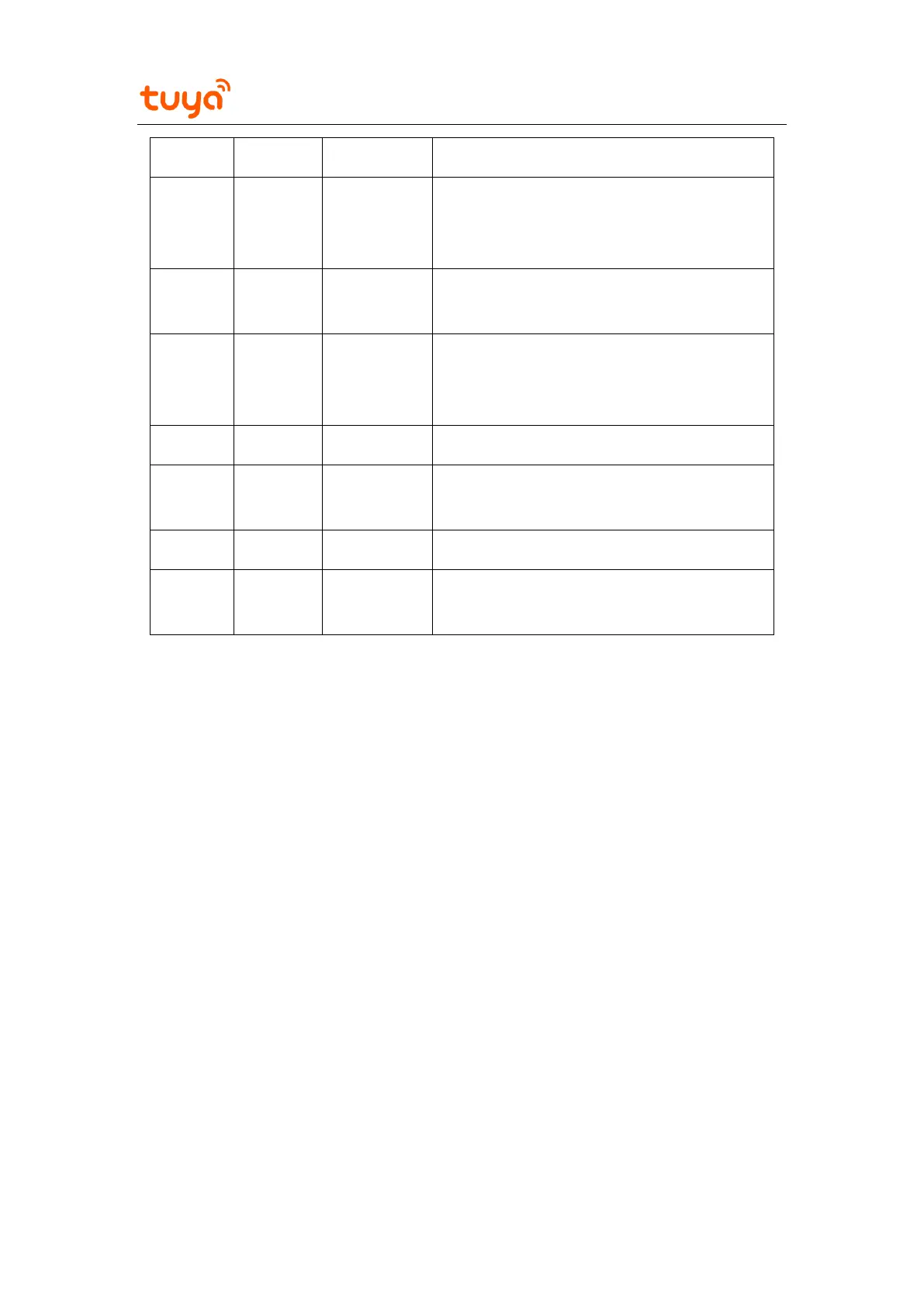
UART_RX, which is connected to GPIO27
(pin 16) on the IC (See the following Note
3.)
GPIO_25, a standard PWM pin, which is
connected to GPIO25 (pin 31) on the IC
UART_TX, which is connected to GPIO26
(pin 24) on the IC (See the following Note
3.)
ADC pin (See the following Note 2.)
GPIO_24, a standard PWM pin, which is
connected to GPIO24 (pin 32) on the IC
Hardware reset pin (active at a low level)
GPIO_3, a standard PWM pin, which is
connected to GPIO3 (pin 23) on the IC
Note:
1. P indicates power supply pins, I/O indicates input/output pins, and AI indicates analog
input pins.
RST is only a hardware reset pin and cannot clear the Wi-Fi network configuration.
2. This pin can only function as an ADC input and not a common I/O. If this pin is not
used, it must be disconnected.
When this pin is used as the ADC input, the input voltage range is 0 V to 2.0 V.
3. The UART pins are user-side serial interfaces.