electroplated to keep a good conducting circuit.
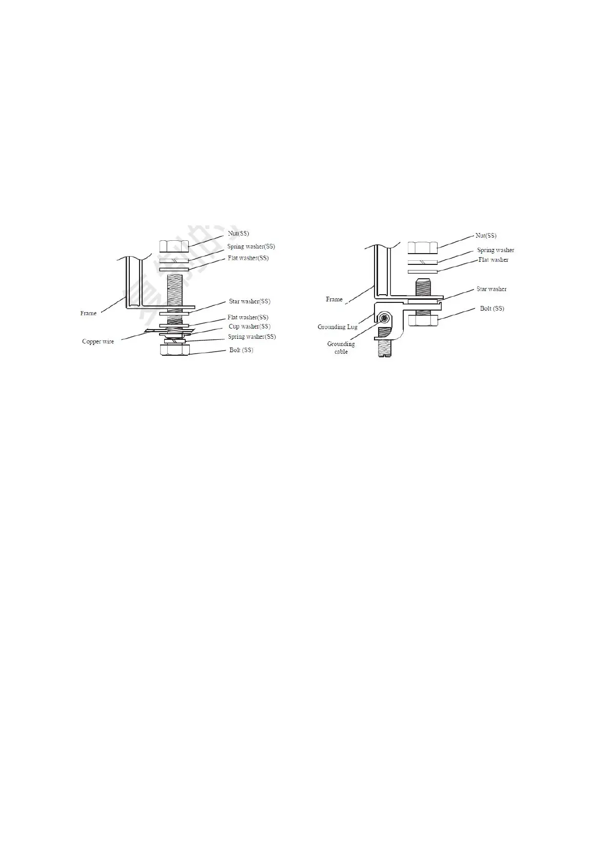
Use suitable grounding conductors to connect the Module frame to the mounting structure.
This can achieve proper grounding effects.
The grounding conductor must be connected to ground via an appropriate grounding
electrode. It is recommended to use lugs to connect the grounding cables. If it is only
mechanically connected to a grounded module without bolts and nuts, the mounting system
should be grounded as well.
First, peel the grounding cable to a proper length without damage to the metal core. Then
insert the peeled cable into the lug, tighten the screw. As shown in Figure 8, connect the lug
to the aluminum frame with stainless steel bolts and connection components.
▐ 07 BYPASS DIODESAND BLOCKDIODES
◊ In a system with two or more Modules connected in series, if part of a Module is shaded
while the other part is exposed to the sun, a very high reverse current will go through the
cells which have been partly or entirely covered and it will cause overheat on the cells,
which may damage the Module. Using bypass diodes can protect Modules from this kind
of risk. There are bypass diodes in junction boxes, which can reduce the effects of partial
shadows. Do not privately disassemble the junction box to replace the diodes, even when
the diodes are broken. This should be processed by the professionals.
◊ In a system with batteries, if the controller doesn’t have the function of backswing
protection, block diodes installed between the battery and the Module can prevent the
reverse current from damaging the Module.