ISC and VOC marked on the Module should be multiplied by a factor of 1.25 when to
determining component voltage ratings, current ratings, fuse sizes, and size of controls
connected to the PV output.
Completely cover the Modules with an opaque material to prevent electricity from being
generated during disassembling the conductors.
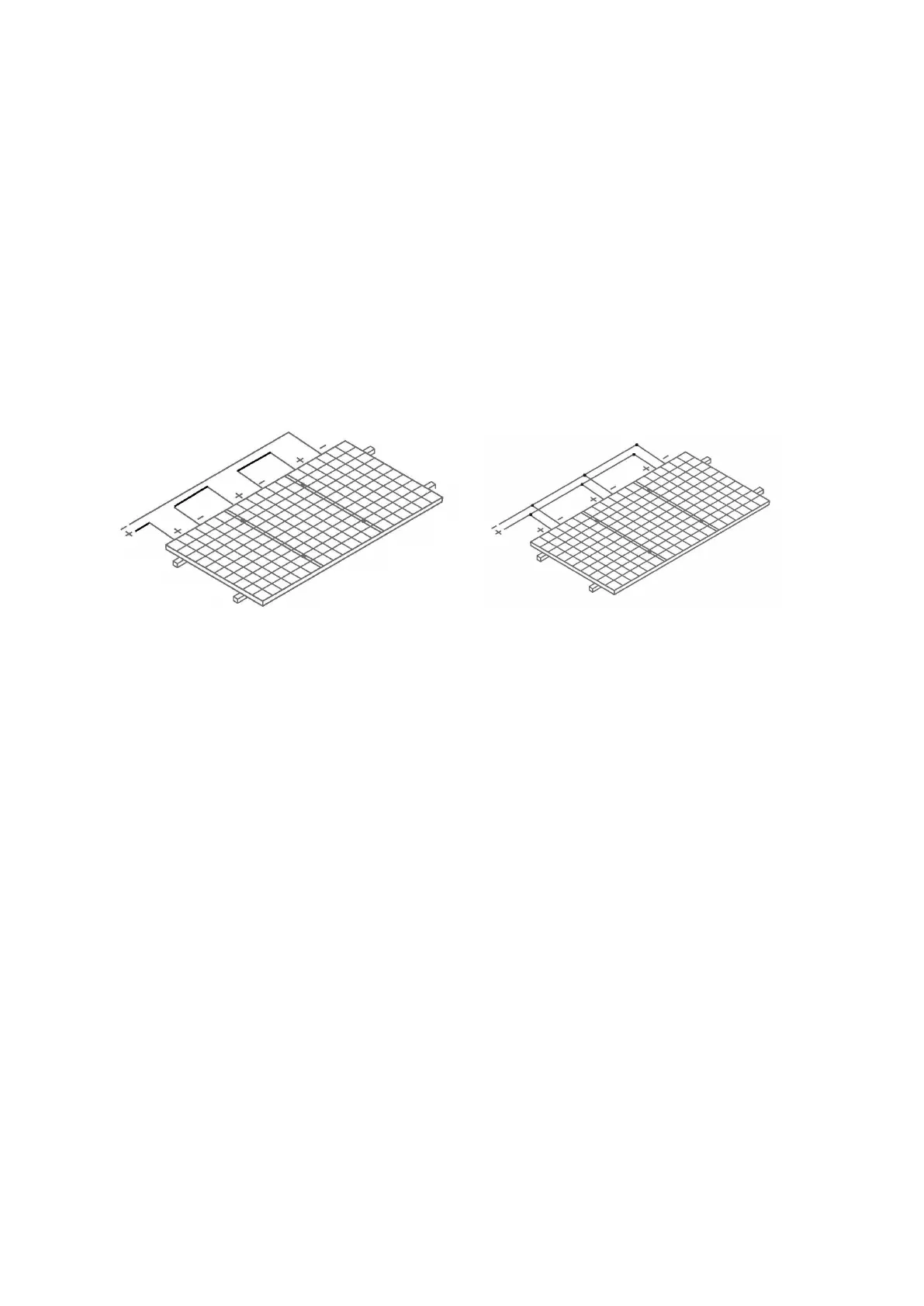
It is not allowed to use the Modules in different models in the same solar photovoltaic
system. When the Modules are connected in series, the voltage of every string shall not be
higher than the maximum voltage of the system (as shown in Figure 5). Reference equation
of the maximum number of the Modules in serial connection: maximum system voltage of
the module/ (1.25* open-circuit voltage).
When connected in parallel, the current output is equal to the sum of each string’s current
(as shown in Figure 6). Fuse is necessary for each module string. Take reference to the
local regulation. Recommended maximum parallel Modules configurations: Fuse rating/
(1.25* short-circuit current).
Figure 5 Connection in Series
Figure 6 Connection in parallel
Refer to the local regulations to determine the system wire size, types and temperatures.
The cross section of the cables and the capacity of the connectors must be selected to suit
the maximum system short circuit current (The recommended section area for a single
piece of Module is 4 mm
2
, and the recommended rated current for the connector is greater
than 20A), otherwise the cables and connectors shall be overheated under large current.
Caution: The maximal temperature of the cable is 85 ℃ while the upper limited
temperature of the connector is 105℃.
Make sure the electric components such as the connectors and inverters are off-state during
the installation. To reduce lightning damage, the loop area should be kept as small as
possible when laying cables. It is recommended to use fuses in each string.
▐ 06 GROUNDING
6.1 Grounding by cable
• The grounding bolts must be made of stainless steel and be used in the specified grounding
holes. First, make the stainless steel bolt pass through the spring washer, cup washer, flat
washer, and star washer, and then insert through the grounding hole, flat washer and spring
washer on the frame. Finally, tighten with a nut. Caution: The upper limited temperature of
the conductor is 85 ℃ . As for the installation, refer to Figure 7.
6.2 Grounding by lugs
All the module frames and mounting structures shall be grounded according to regional and
national electricity regulations. Use recommended hardware to connect grounding cables
and fasten to the Module frames.
While using the metal structure, make sure the surface of the system have been
 Loading...