Recommended bolt kits are as follows:
Material: Stainless steel Or
Hot galvanizing
bolt tightening torque
range:(N.m)
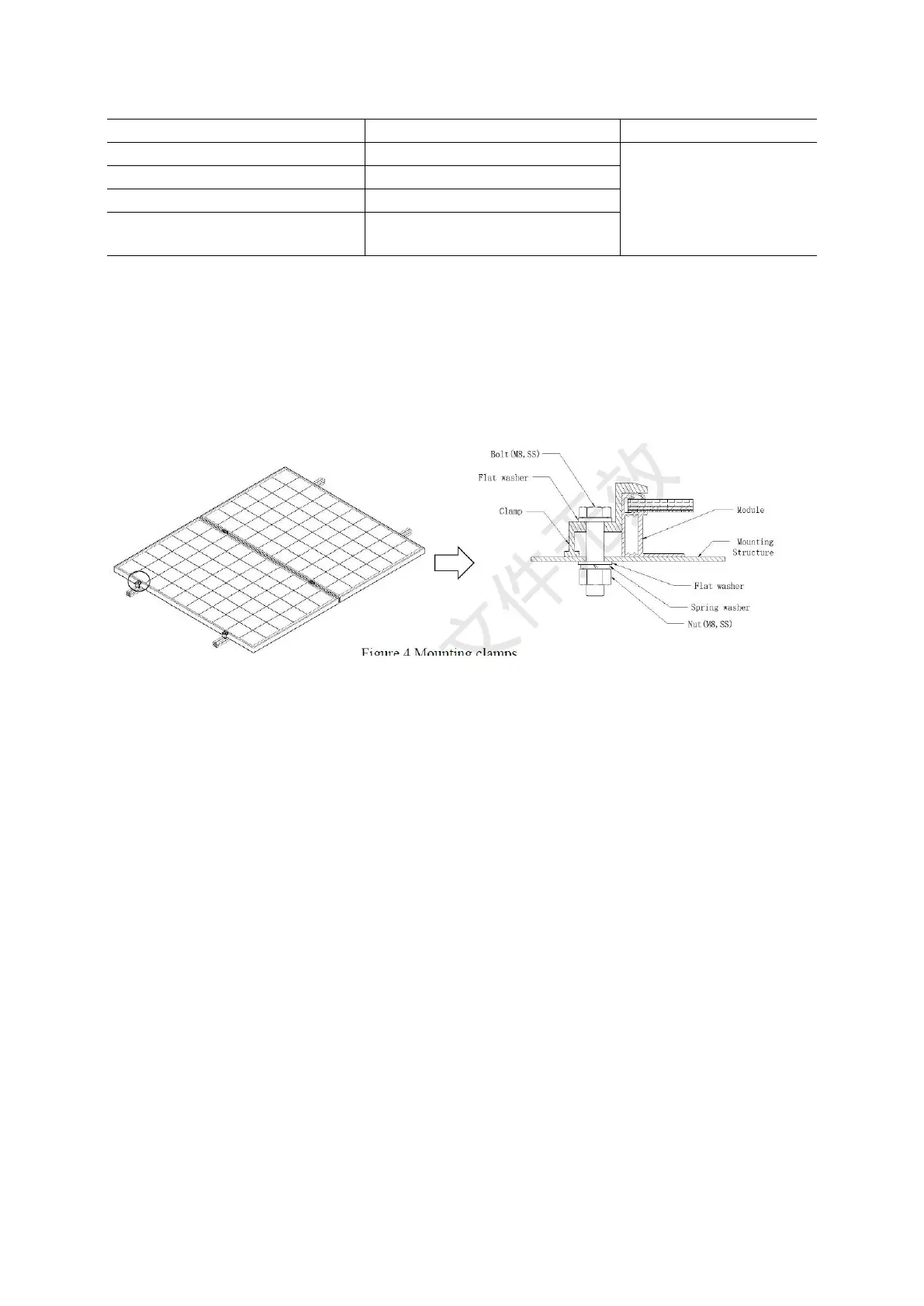
♦ Clamping system: use proper clamp, and fix the module with the installation support, as
shown in Fig. 4.
The clamp must maintain an overlap of unless 10 mm with the frame of the module (you
can change the cross section of the clamp if the module is securely installed). The applied
value of torque should refer to mechanical design standard and the bolt type customer is
using, for example: M8: 16-20 N•m.
Figure 4 Mounting clamps
▐ 05 Electrical Installation
◊ DC power generated by the photovoltaic system can be converted into AC power and fed
into the grid. Policies on connecting renewable energy system to the grid vary from region
to region. Consult senior system designer before designing the system. Generally, the
system installation shall be formally approved by the local public sector.
5.1 General Installation
Installation structure should be compatible with module, in order to avoid galvanic
corrosion. Any defects caused by such corrosion will void the warranty.
The DC-side system potential of the photovoltaic array includes the practice of floating
ground, positive-pole grounding and negative-pole grounding according to the system
requirements; and different cell technologies have different adaptability. In a power-station
project, particularly the module of the crystalline silicon photovoltaic cells, too large an
absolute value of the negative to the ground might cause potential induced degradation
(PID). Consequently, it is appropriate to use the negative grounding system so that the
potential of the circuit is positive. Consult the inverter manufacturer for details.
It is forbidden for non-professionals to open the lock nuts of the connector. Make sure that
the connectors are clean, dry and fully connected (A click sound should be heard when
fully connected), otherwise it may lead to electric arc sparks which will damage the
connector or cause a fire.
Under normal conditions, a module is likely to experience conditions that produce more
current and/or voltage than reported at standard test conditions, Accordingly, the values of
 Loading...