EasyManua.ls Logo

TW SOLAR TWMND54HS430 - Page 16

Default Icon
21 pages
Print Icon
To Next Page IconTo Next Page
To Previous Page IconTo Previous Page
Loading...
Table 4 Mounting dimension and load capacity
Classification
Modules model
Height
of the
frame
(mm)
The mounting
clamp position
M(mm)
The mounting
clamp position
N(mm)
Installation Method E
Test load: front/back
Pa
Installation Method F
Test load: front/back
Pa
Bifacial
Module
TWMPD-60HD
TWMND-60HD
B30
1200
1096
5400/2400
--
1400
1096
5400/2400
--
TWMPD-66HD
TWMND-66HD
B30
1200
1096
5400/2400
±2400
1400
1096
5400/2400
3600/2400
TWMPD-72HD
TWMND-72HD
B30
1200
1096
5400/2400
--
1400
1096
5400/2400
--
B35
1200
1096
5400/2400
±2400
1400
1096
5400/2400
3600/2400
TWMPD-78HD
TWMND-78HD
B30
1200
1096
5400/2400
--
B35
1200
1096
5400/2400
--
TWMPF-50HD
B35
1400
1055
5400/2400
--
TWMPF-55HD
B35
1400
1055
5400/2400
3600/2400
TWMPF-54HD
B35
1400
1262
5400/2400
--
TWMPF-60HD
B35
1400
1262
5400/2400
3600/2400
TWMPF-66HD
TWMHF-66HD
B35
1400
1262
5400/2400
3600/2400
Note: Test load = γm(safety factors) × design load.
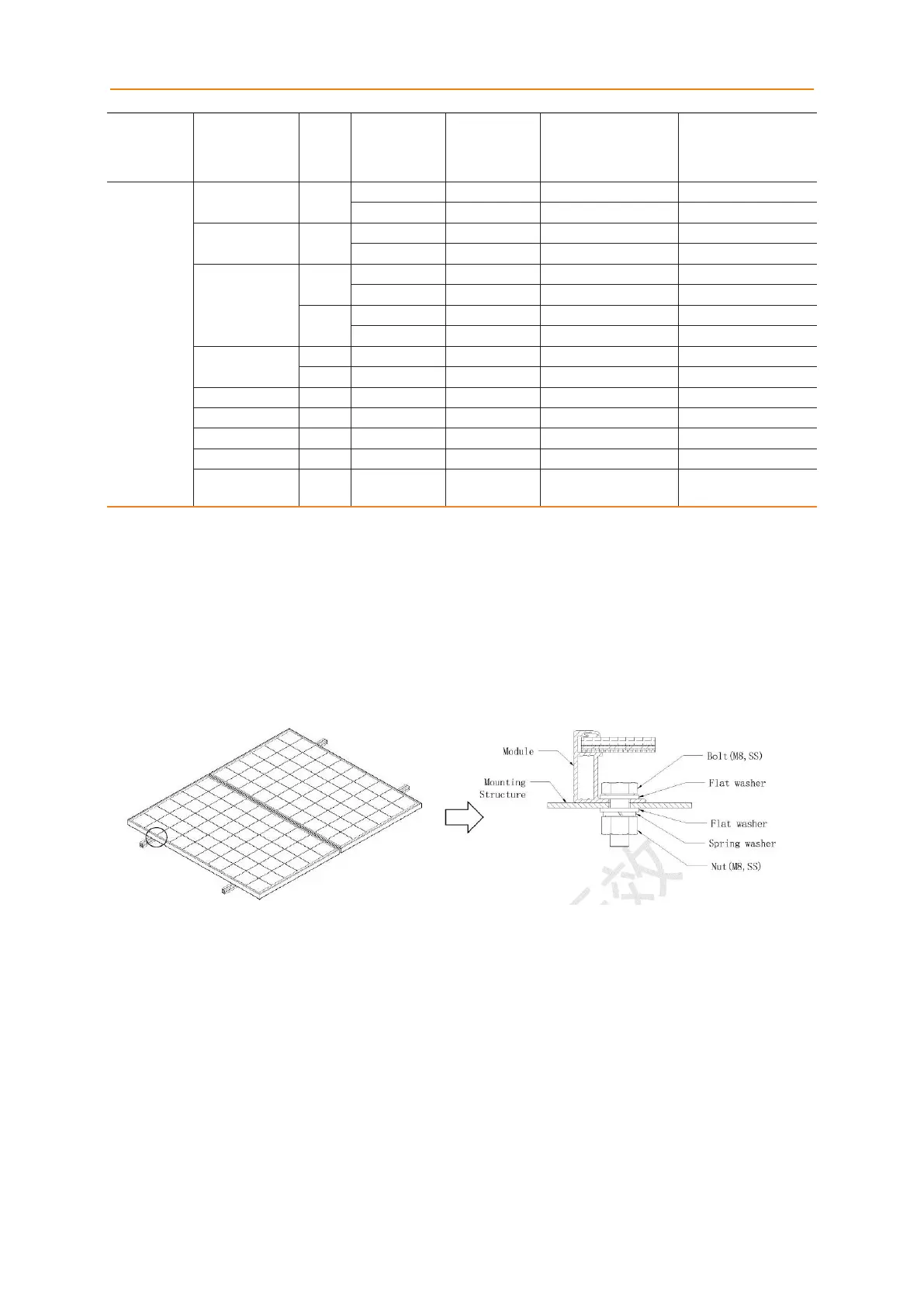
The Modules may be installed and fixed with the following methods:
Mounting hole system: Use the corrosion-resistant bolt, for fixing with the installation
support through the installation hole in the side frame of the module, as shown in Fig. 3.
Figure 3 Mounting holes

Related product manuals