2
Twin City Engineering Supplement ES-52
Housing should be lifted using straps and spreaders. Do
not distort housing or side plates when lifting.
Bearing pedestals should be lifted using straps or pad-
ded chains. Under no circumstances should an attached or
separated bearing pedestal be lifted by the shaft, bearings,
drives, motor or wheel.
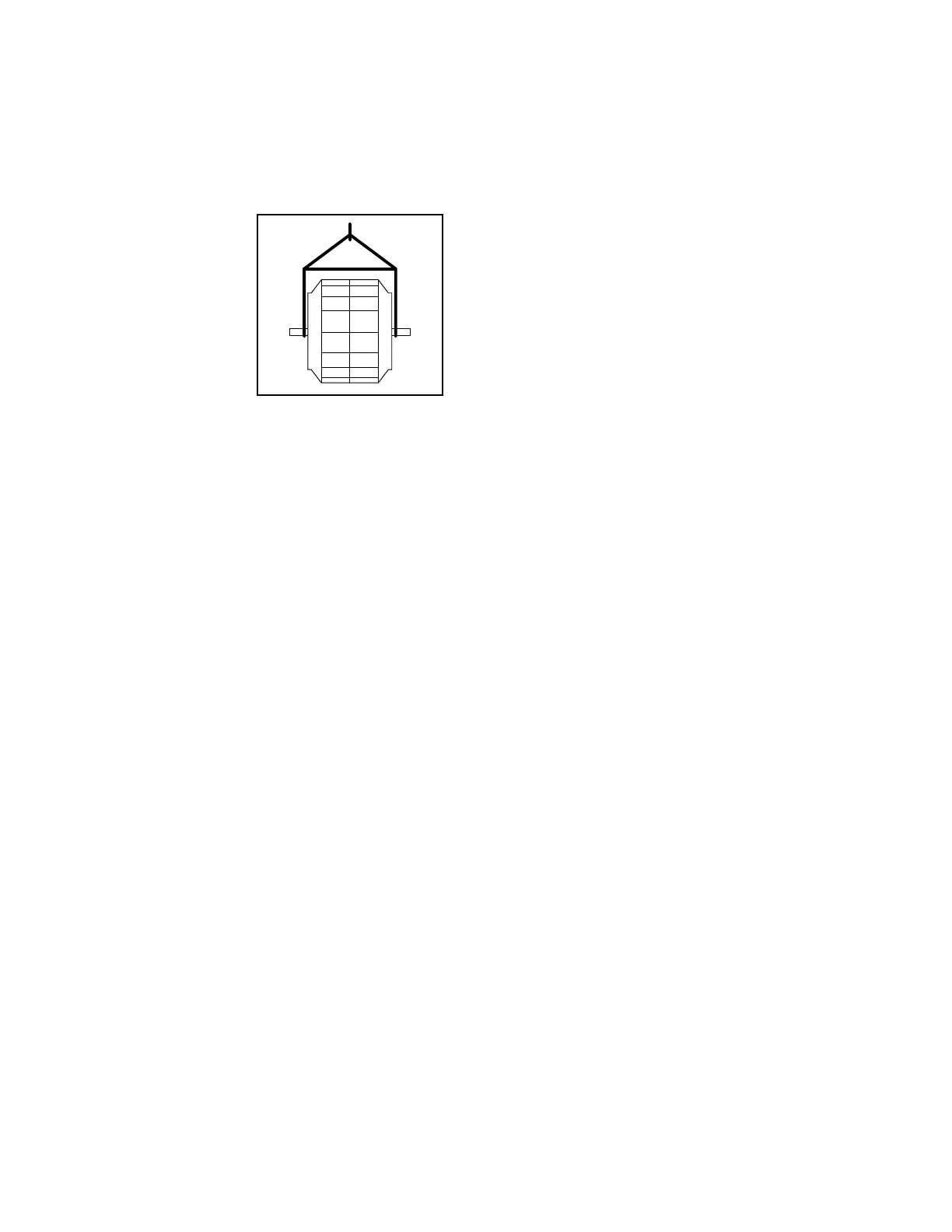
The shaft and wheel assembly may be lifted using
a hoist and a spreader
with a sling around the
shaft at points nearest the
wheel (see Figure 2). Take
care not to scratch the
shaft where the wheel or
bearings will be mounted.
Never lift or support the
assembly by the wheel.
Always support the assem-
bly by the shaft when lifting
or storing. Do not support
the shaft or the wheel on
housing sides. Use only the
key provided with the shaft
and wheel.
Wheels shipped separately can be lifted by slings run-
ning through the blades and around the hub. Never lift the
wheel by blades or flanges. Always transport wheels by
lifting. Do not roll the wheel as this can damage coatings
and change the balance of the wheel.
Bent shafting is a source of vibration and bearing failure,
so handle the shaft with care. Any scratches on the shaft
may be removed with fine emery cloth or a stone.
Short Term Storage
If fan installation is to be delayed, store the unit in a
protected area. Protect the fan and motor bearings from
moisture and vibration (or shock loading).
Long Term Storage
Prior to Storage – Fan bearings (and motor bearings per
the motor manufacturer’s specifications) are to be greased
at the time of going into extended storage. On belt drive
units the belt tension should be reduced to less than half
the specified value for the fan’s design to prevent a sag/
set from forming in the shafts and belts.
If the unit was supplied with a motor, the motor windings
should be measured at this time and recorded for
comparison prior to placing in service. If the fan housing
was supplied with a drain connection, this plug should
be removed to prevent any moisture from accumulating in
this portion of the unit during storage.
Storage Procedure – Fans should be stored indoors when-
ever possible where control over temperature, shock and
dust is reasonably maintained. If units are to be stored
outside in the elements, they should be covered with a
water-resistant material. The bearings should be shielded
individually from water and dirt; however, do not tightly
seal to avoid trapping condensation. Stored equipment
should be stored on a clean, dry floor or blocked up off
the ground on blocks to prevent unit from setting in any
water or directly on the ground. If shock or vibration will
be present during storage, the unit may need to be placed
on some type of vibration dampening material to aid in
preventing brinelling of the bearing surfaces.
Periodic Check – On a monthly interval, the equipment
should be checked to ensure that it has remained in an
acceptable stored condition. The fan (and motor if sup-
plied) should be rotated several times by hand while add-
ing enough grease to replenish the bearing surfaces with
fresh grease and to maintain a full bearing cavity. Grease
used must be compatible with that already supplied in the
motor and fan bearings. The fan impeller should be left
at approximately 180 degrees from that of the previous
month to prevent the shaft and impeller from taking a
set in one position. Storage records should be maintained
which indicate the above requirements have been followed.
Consult the motor manufacturer for proper storage, space
heater connection and lubrication if the unit was supplied
with one.
Start-Up – When the unit is removed from storage, all fan
bearing grease should be purged and replenished with fresh
grease as per the lubrication decal. The motor should be
measured to verify that the resistance is still at a satisfac-
tory level compared to the value recorded prior to storage.
Spherical roller bearings with split pillow block housings
should be recharged with grease. The bottom half of the
housing should be 1/3 full.
Foundations and Supporting Structures
Floor mounted fans should be installed on a flat, level, rigid
concrete foundation with a mass at least three to five times
that of the assembly supported as a guide, depending on
the size and speed of the fan. Foundation shall be suitable
for static and dynamic loads and foundation frequencies
be separated at least 20% from the rotational speed/speed
ranges. The plan area should be no more than twice that
required by the equipment. Foundations with larger areas
should have correspondingly larger mass. Anchor bolts
should be “L” or “T” shaped with sufficient length for nuts,
washers, shims, and threads for draw-down. Each bolt
should be placed in a sleeve or pipe with a diameter larger
than the bolt to allow for adjustment.
If the fans are mounted on a sub-structure, an inertia
base with spring isolator system should be considered.
Fans mounted to or within a structure should be placed
as close as possible to a rigid member such as a wall or
column. The structure must be designed for rotating equip-
ment; static design for strength is not sufficient to insure
proper operation. Supports for suspended fans must be
cross-braced to prevent side sway. Structural resonance
should be at least 20% from fan operating speed. Vibration
isolators should be used where applicable.
Any ducting should have independent support; do not
use the fan to support ducting. Isolating the fan from
ductwork with flex connections eliminates transmission of
vibration. Fans handling hot gases require expansion joints
at both the inlet and discharge to prevent excessive loads
caused by thermal growth.
For fans requiring concrete filled bases or pedestals,
please refer to Twin City Fan's installation and mainte-
nance manual "Heavy Duty Centrifugal Fans - ES-995"
for instructions.
Fan Installation – Factory Assembled Units
Follow proper handling instructions given earlier.
1. Move the fan to the final mounting position.
2. Remove skid, crates, and packing materials carefully.
3. If supplied, place vibration pads or isolation base on
mounting bolts. Line up holes in fan base with bolts.
4. Place fan on mounting structure. Carefully level unit
using shims as required at all mounting hole locations.
Bolt down the unit. Be careful not to force the fan to
conform to the mounting structure/foundation. This may
cause the bearings to become misaligned or pinched
causing vibration and premature failure.
5. Any grout may now be used. Bolt the fan in position
before applying grout. Do not depend upon grout to
support rotating equipment.
6. Continue with Operations Checklist.
Figure 2. Moving Shaft and
Wheel with Spreader Bar



 To Next Page