EasyManua.ls Logo

Tyco Rovalve S20 - User Manual

Tyco Rovalve S20
9 pages
Print Icon
To Next Page IconTo Next Page
Loading...
Rovalve S20
Installation and Maintenance Instructions
Tyco reserves the right to change the contents without notice ROVMC-6614-EN-0904
1. General information
The ROVALVE S20 knife gate valve is a UNIDIRECTIONAL (one-way shut-off) product.
Unidirectional valves have a preferred shut-off direction.
CAUTION
Care must be taken in valve installation with respect to direction of flow.
Unidirectional valves have the preferred direction of shut-off
indicated by the word "SEAT" cast into the valve body or the
word "SEAT" stamped on the upper right hand corner of the gate
on the seat side. A unidirectional valve is normally installed with
the seat side (preferred direction) downstream, with the line
pressure pushing the gate toward the seat.
CAUTION
The user is responsible for correct directional installation.
On select applications, including low pressure - dry solids applications, greater performance may
be realized by installing the S20 in the reverse flow position. Valves supplied with backing rings are
normally installed in a reverse flow orientation, with the seat side of the valve upstream. Contact
factory for details and additional recommendations.
Initial inspection:
1. Examine entire valve and report any damage or discrepancies immediately.
2. Accessories, if any, including solenoids, limit switches, positioners, etc., are tested for
functionality prior to shipment. Examine carefully for damage which may occur during shipment.
3. Operators: Standard manual handwheels may be shipped loose for field installation. It is
necessary to use a pipe wrench or large crescent wrench to properly tighten the handwheel
retaining nut. Be sure to fully tighten.
4. Packing assembly: The packing gland bolts should be checked and adjusted to obtain a first
time packing seal. Packing gland bolts and or nuts may become slightly loose when valve is
shipped. Field adjustment is expected and desired. Tighten each nut equally just enough to
stop any leakage. Overtightening may increase valve operating torque and shorten packing life.
Thank you for purchasing a ROVALVE S20
knife gate valve product from Tyco Flow
Control. With proper care it should provide
you a long service life.
www.tycoflowcontrol.com
Index
1. General information 1
2. Installation instructions 2
3. General maintenance 4
4. Spare parts 4
5. Instructions for repacking 5
6. Stem nut replacement
instructions 6
7. Suggested cylinder support when
cylinder is mounted horizontal 7
8. Instructions for converting a
MH to bevel gear operator 8
9. Recommended long term storage
procedure 9
Tables and figures
Table A: Maximum flange bolt torques 2
Table B: Knife gate valve dimensions,
per MSS-SP81 3
Table C: Valve dimensions 3
Table D: Packing sizes 5
Figure 1, Retaining nut assembly 1
Figure 2, Packing gland nuts 1
Figure 3, Blind-tapped holes 2
Figure 4, Flange bolts 2
Figure 5, Envelope dimensions 3
Figure 6, Inspection points 4
Figure 7, Spare parts-topworks 4
Figure 8, Spare parts-valve body 4
Figure 9, Repacking instructions 5
Figure 10, SM636 packing 5
Figure 11, Stem nut replacement
instructions 6
Figure 12, Pin-style lockouts 8
Figure 13, BG conversion 8
Figure 1 Figure 2
Assemble handwheel,
be sure and fully
tighten handwheel
retaining nut
Inspect and tighten packing
gland nuts to stop any
leakage.
Question and Answer IconNeed help?

Do you have a question about the Tyco Rovalve S20 and is the answer not in the manual?

Summary

General Information

Initial Inspection and Handling

Examine valve for damage, test accessories, check operators and packing.

Directional Installation CAUTION

Warning about careful installation based on SEAT marking to prevent damage.

Installation Instructions

Installation Procedures

Steps for aligning flanges, using gaskets, and proper bolting to avoid valve body damage.

Flange Bolting CAUTION

Warning against using bolts too long or over-torquing to prevent valve body damage.

General Maintenance

Maintenance Checks and Lubrication

Regular inspection of stems, packing glands, and valve operation, including lubrication points.

Spare Parts

Spare Parts Ordering Information

Recommended spare parts and details needed for ordering replacement parts for valves or operators.

Instructions for Repacking

Valve Repacking Procedure

Detailed steps for valve repacking, including tool requirements and packing installation.

Stem Nut Replacement Instructions

Stem Nut Replacement Guide

Step-by-step instructions for disassembling and reassembling the stem nut assembly.

Suggested Cylinder Support Methods

Horizontal;Off-Vertical Cylinder Support

Suggestions for supporting cylinders in horizontal or off-vertical positions to maintain alignment and prevent failure.

Converting MH to BG Valves

Bevel Gear Conversion Procedure

Steps for converting a manual handwheel (MH) valve to a bevel gear (BG) operator.

Recommended Long Term Storage Procedure

Storage for Handwheel;Bevel Gear Valves

Guidelines for storage facility, orientation, preparation, inspection, and maintenance for handwheel or bevel gear operated valves.

Storage for Cylinder Operated Valves

Guidelines for storage facility, orientation, preparation, inspection, and maintenance for cylinder operated valves.

Overview

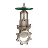
The Rovalve S20 is a knife gate valve manufactured by Tyco Flow Control, designed for unidirectional shut-off applications. This manual provides comprehensive instructions for its installation, operation, and maintenance, ensuring a long service life.

Function Description:

The Rovalve S20 is a unidirectional knife gate valve, meaning it has a preferred shut-off direction. This direction is indicated by the word "SEAT" cast into the valve body or stamped on the upper right-hand corner of the gate on the seat side. Typically, the valve is installed with the seat side downstream, allowing line pressure to push the gate toward the seat for effective sealing. However, for specific applications, such as low-pressure dry solids, the valve may be installed in a reverse flow position, with the seat side upstream, especially when supplied with backing rings. The valve is suitable for use in both vertical and horizontal lines.

Important Technical Specifications:

  • Unidirectional Operation: Designed for one-way shut-off, with a clear "SEAT" marking for correct installation.
  • Flange Compatibility: The port flanges for 2" through 24" valves are drilled and tapped to ANSI B16.5/150 standards. For 30" and 36" valves, the flanges conform to MSS-SP44, with face-to-face dimensions per MSS-SP81.
  • Blind-Tapped Holes: The bolt holes in the chest or upper flange area are blind-tapped, requiring careful selection of bolt length to prevent damage to the valve body or gate.
  • Maximum Flange Bolt Torques: Specific torque values are provided for different bolt sizes, ranging from 55 +/-5 foot-pounds for 5/8" bolts to 250 +/-5 foot-pounds for 1 1/2" bolts, to ensure proper sealing without deforming or fracturing the body.
  • Valve Dimensions: Detailed tables (Table B and Table C) provide flange diameter, raised face diameter, bolt circle diameter, number of bolt holes, thread size/thread, face-to-face dimensions, flange thickness, and overall valve dimensions (A, B, C, D, E, F) and weight for various valve sizes (2" to 36").
  • Packing Sizes: Table D specifies the number of rows, cross-section, and cut length for packing for different valve sizes, ensuring proper fit and sealing.
  • SM636 Packing: For valves equipped with SM636 packing, it is triangular in shape (1/2" equilateral on a side and about 2-1/2" long) and can be broken into pieces to conform to the packing box. It is crucial to fill all voids during installation.

Usage Features:

  • Installation Flexibility: Can be installed in vertical or horizontal lines. However, if the operator is not vertical, additional support may be required, especially if not handwheel operated.
  • Alignment Importance: Mating line flanges must be properly aligned before installation to prevent damage. Pipe supports and/or expansion joints should be used to minimize pipe loads.
  • Bolt Length Caution: When installing studs or bolts in the blind-tapped holes, it is critical to use correct lengths to avoid pinching the valve body, forcing the body wall into the gate, or springing the gate out of line, which can lead to scoring or scratching of the gate face. Studs are recommended for all tapped bolt holes, particularly the upper chest holes.
  • Handwheel Assembly: Manual handwheels may be shipped loose and require proper tightening of the retaining nut using a pipe wrench or large crescent wrench.
  • Cylinder Support: For horizontal or off-vertical cylinder-mounted valves, additional support is necessary to prevent premature failure of the cylinder and/or valve. Various support methods, including turnbuckles, saddle-style hangers, and alternate head-supports, are suggested to maintain alignment and support the cylinder's bulk weight. Tie-rod mounted supports are not recommended for spring-style cylinder actuators.
  • Pin-Style Lockouts: If equipped, pin-style lockouts (L1, L2, L3) can secure the gate in open or closed positions during disassembly, preventing unwanted movement. L6 refers to a case-hardened pin for use with L1, L2, or L3.

Maintenance Features:

  • Regular Inspection: All Rovalve products should be inspected at least every 60 days. Key areas to check include valve stems, extension stems, stem nut, and packing gland.
  • Lubrication: Valve stems require lubrication. A grease fitting is provided in the yoke hub for standard bearing grease (ASTM 4950 GBLB) to lubricate the stem and stem nut assembly. Additional lubrication can be applied directly to stem or stem threads.
  • Packing Gland Adjustment: Check for leaks or worn packing. If leakage occurs, equally tighten the packing gland nuts to stop leakage without overstressing the bolting.
  • Repacking Instructions: Detailed instructions are provided for repacking the valve, including tools required (wrenches, square braided packing, knife, flat bar, radius end tool), safety precautions, and steps for preparing the valve, removing old packing, and installing new packing. It emphasizes cutting packing to exact length, tamping it evenly, alternating sides where packing ends meet, and tightening the gland only enough to stop leakage after line pressure is applied.
  • Stem Nut Replacement: Simple instructions for replacing the stem nut assembly without removing the entire yoke assembly. This involves removing the handwheel, retainer bolts, and retainer, then rotating the old stem nut off and the new one on.
  • Bevel Gear Conversion: Instructions for converting manual handwheel (MH) valves to bevel gear (BG) operated valves. This process is straightforward and does not require removing the 4-Post yoke assembly. Conversion kits include the bevel gear operator with an integral thrust-style stem nut, mounting plate, bolts, and handwheel/drive nut.
  • Long-Term Storage: Recommendations for storage procedures (1 to 5 years) to maintain product integrity. For handwheel or bevel gear operated valves, a clean, dry protected warehouse is preferred. For cylinder operated valves, the preferred orientation is fully open and vertical to support the rod and prevent "flat spots" on seals. Cylinder ports should be lubricated and plugged. Semiannual visual inspections are recommended, checking packaging, flange covers, dryness, and cleanliness. Maintenance involves correcting deficiencies and recording actions.

Tyco Rovalve S20 Specifications

General IconGeneral
BrandTyco
ModelRovalve S20
CategoryIndustrial Equipment
LanguageEnglish

Related product manuals