Rovalve S20
Installation and Maintenance Instructions
Tyco reserves the right to change the contents without notice page 3
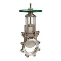
Figure 5
Table B MSS-SP81 dimensions rovalve
Valve Flange Raised Bolt Circle No. bolt Thread Face to Flange
size diameter face diameter holes size / thread face thickness
2 6 3-5/8 4-3/4 4 5/8-11 NC 1-7/8 1/2
3 7-1/2 5 6 4 5/8 -11 NC 2 1/2
4 9 6-3/16 7-1/2 8 5/8 -11 NC 2 1/2
5 10 7-5/16 8-1/2 8 3/4 -10 NC 2-1/4 5/8
6 11 8-1/2 9-1/2 8 3/4 -10 NC 2-1/4 5/8
8 13-1/2 10-5/8 11-3/4 8 3/4- 10 NC 2-3/4 5/8
10 16 12-3/4 14-1/4 12 7/8 -9 NC 2-3/4 3/4
12 19 15 17 12 7/8 -9 NC 3 3/4
14 21 16-1/4 18-3/4 12 1 -8 NC 3 13/16
16 23-1/2 18-1/2 21-1/4 16 1 -8 NC 3-1/2 7/8
18 25 21 22-3/4 16 1 1/8-7 NC 3-1/2 15-/16
20 27-1/2 23 25 20 1 1/8-7 NC 4-1/2 1
24 32 27-1/4 29-1/2 20 1-1/4-7 NC 4-1/2 1
30 38-3/4 33-3/4 36 28 1-1/4-7 NC 4-5/8 1-1/8
36 46 40-1/4 42-3/4 32 1-1/2-6 NC 4-5/8 1-1/8
Table C valve dimensions
Valve size A B C D E F Weight
2 8 6 1-7/8 12 14-1/4 2-3/4 18
3 8 7-1/2 2 13-3/4 17 2-7/8 22
4 8 9 2 15-1/2 19-3/4 2-7/8 28
6 12 11 2-1/4 20-5/8 26-7/8 3-3/4 53
8 12 13-1/2 2-3/4 24-3/8 32-5/8 3-5/8 72
10 16 16 2-3/4 28-3/4 39 4-1/2 109
12 16 19 3 32-1/4 44-1/2 4-1/2 146
14 20 21 3 35-1/2 49 8 225
16 20 23-1/2 3-1/2 38-7/8 54-1/4 5-3/4 288
18 20 25 3-1/2 43 60-3/8 10 356
20 20 27-1/2 4-1/2 47 66-1/2 11-3/8 488
24 20 32 4-1/2 54-1/2 77-3/4 15-5/8 723
30 18 38-3/4 4-5/8 74-3/4 95-1/4 18 1303
36 18 46 4-5/8 87-3/4 113-7/8 12 1842
Note 1) These dimensions duplicate ANSI B16.5/150 flange drilling
Note 2) Flange thickness includes 1/16" raised face
Note 3) Through bolt flange drilling is bolt size plus 1/8".
Note: 30" and 36" are standard with bevel gear actuator, Dimension D is centerline to top of 18" diameter handwheel.
 Loading...