2019 49 D4OPTRS
CONTROL PANEL COLOR DISPLAY
The engine ECU will take control of engine throttle and complete the cleaning process.
The manual Regen will be canceled if any of the following occur:
a. Pick-up head is raised
b. Engine RPM increase switch is pressed
c. Engine RPM decrease switch is pressed
d. Regen Inhibit is activated
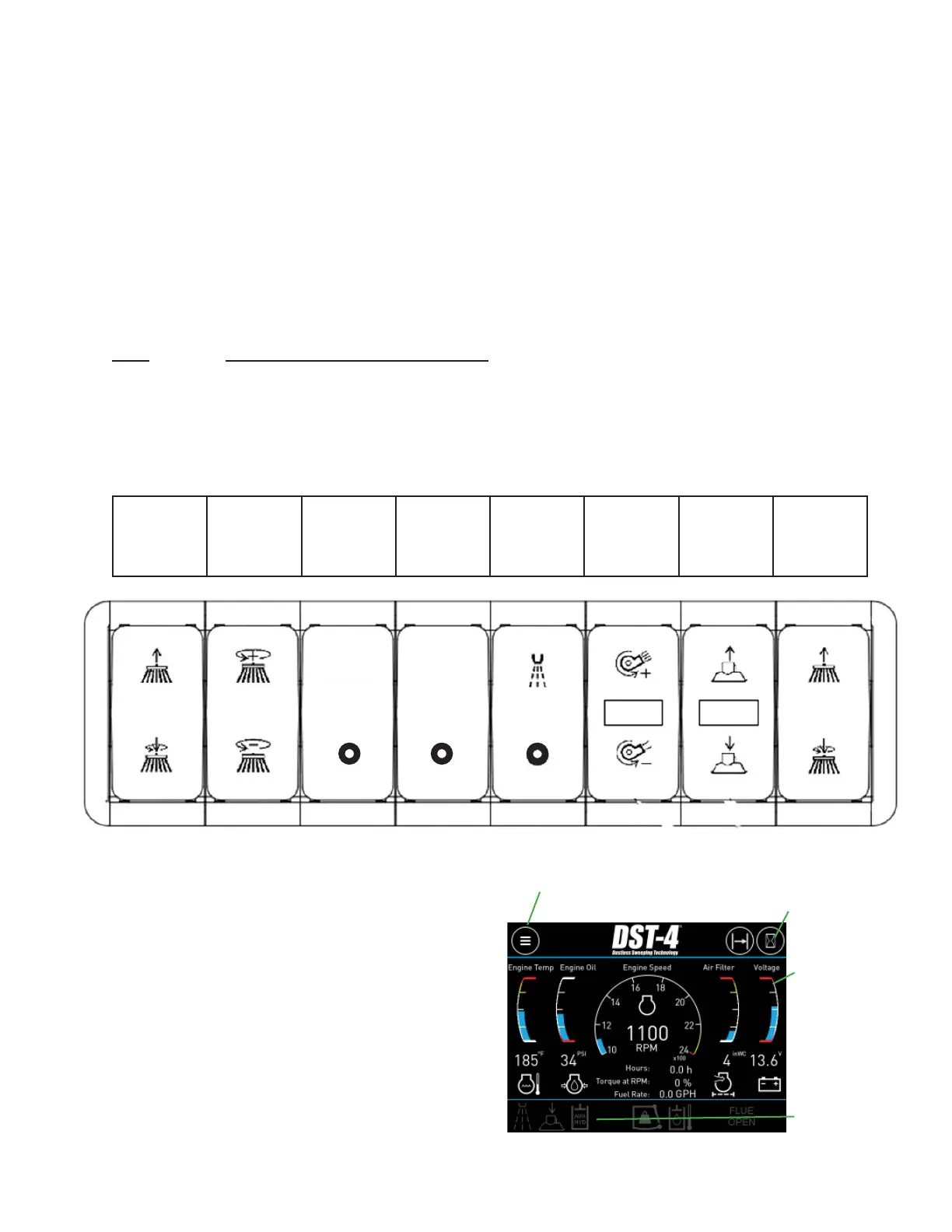
8 Bank Switch Pack Module Diagnostics
The switch pack module communicates each switch position over the CAN datalink to control
module. Each switch controls a function such as gutter broom, pick-up head, etc. The switch
pack has feed back LED indicators for each switch position on all eight switches. Below is a
LED color chart to explain the switch and switch function status.
LED SWITCH / FUNCTION STATUS
OFF: switch inactive, function inactive
CYAN: switch active, function inactive
GREEN: switch active, function active
AMBER: switch active, function stand-by
RED: switch active, function faulted
LEFT
GUTTER
BROOM
UP/DOWN
GUTTER
BROOM
SPEED
UP/DOWN
DST
MODE
PURGE
SYSTEM
WATER
SYSTEM
ON/OFF
BLOWER
RPM
UP/DOWN
PICK-UP
HEAD
UP/DOWN
RIGHT
GUTTER
BROOM
UP/DOWN
The Model DST-4 BlueLogic
®
control
system includes a color human-
machine interface (HMI) display. The
display is used to convey system
information to the user as well as allow
the user to input information to the
control system. The display utilizes
multiple pages to communicate related
groups of information. The operator
can navigate these pages using the
touch screen interface.
Menu
Button
Shortcut to
Hour Meters
Default
Gauges
Indicator
Lights
PURGE
SYSTEM
DST
MODE