Publisher:
Tyro Remotes, 08/2016
Revision number:
4042.V1.3
Manufacturer: Tyro Remotes
Bedrijvenpark Twente 1b, 7602 KA Almelo
6. Programming (an additional or repaired) transmitter to the receiver
PLEASE NOTE: all systems have already been programmed at the factory! You can skip this
part unless you wish to program an additional or repaired hand-held transmitter to the receiver!
If you wish to program an additional or new hand-held transmitter to the Aquarius receiver, take the following steps:
Make sure that the Aquarius is correctly connected and has supply voltage.
Press the black programming button on the bottom of the receiver for 1 second, the status LED on the receiver will light
up red.
Switch on the hand-held transmitter, the LED on the receiver will now flash yellow.
The transmitter is now programmed to the receiver.
Make sure it works by pressing a button, if the status LED on the receiver flashes yellow (± 2x per second), the
programming was successful.
To delete all the transmitters from the memory of the receiver, keep the programming button pressed down for longer than 8 seconds until the
red status LED on the Aquarius switches off.
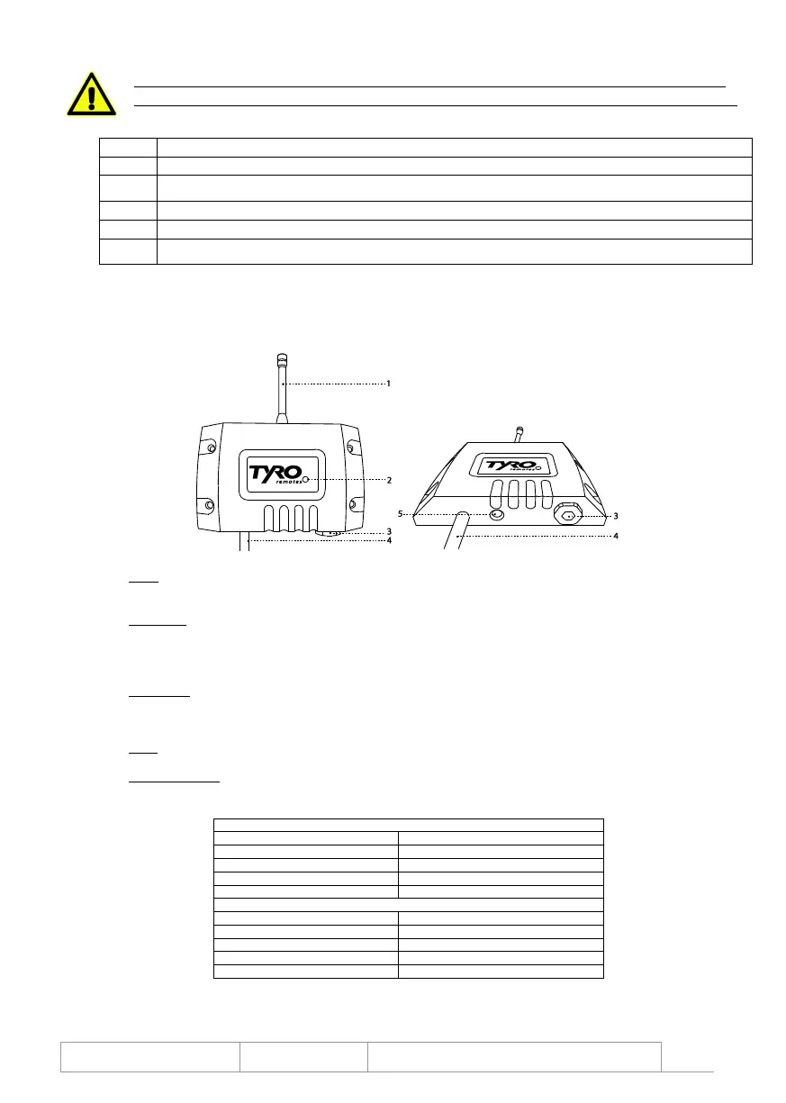
7. Description of Aquarius receiver & system specifications
1. Aerial
This product comes standard with a flexible aerial
The product is also available with a BNC connector to which a BNC aerial or an extension cable can be connected
2. Status LED
This is a double LED that can light up red or yellow
Red constantly on: the receiver is in programming mode
Yellow flashing quickly (± 10x per second): the receiver is receiving a signal from a non-programmed transmitter
Yellow flashing slowly (± 2x per second): the receiver is receiving packets from a programmed hand-held transmitter
3. Fuse holder
This cap can be removed using a flat screwdriver, Allen key no. 8 or open-end wrench no. 19
Behind the cap there is another cap that can be turned 90° anticlockwise using a flat screwdriver
The fuse holder can now be removed and the 10A quickblow glass fuse (5 x 20mm) can be changed
4. Cable
This 10-core cable is used to connect the receiver
5. Programming key
If this is pressed down for 1 second, the receiver goes into programming mode
If it is kept pressed down for longer than 8 seconds, all the programmed transmitters will be deleted from the receiver’s memory
Powersupply / switching voltage
Transmitters per receiver
Transmitter specifications
1x 9V block 600 mAh (Varta Alkaline)
Power usage during transmission
Battery life with normal use
 Loading...