USER GUIDE
System Diagnosis Guide
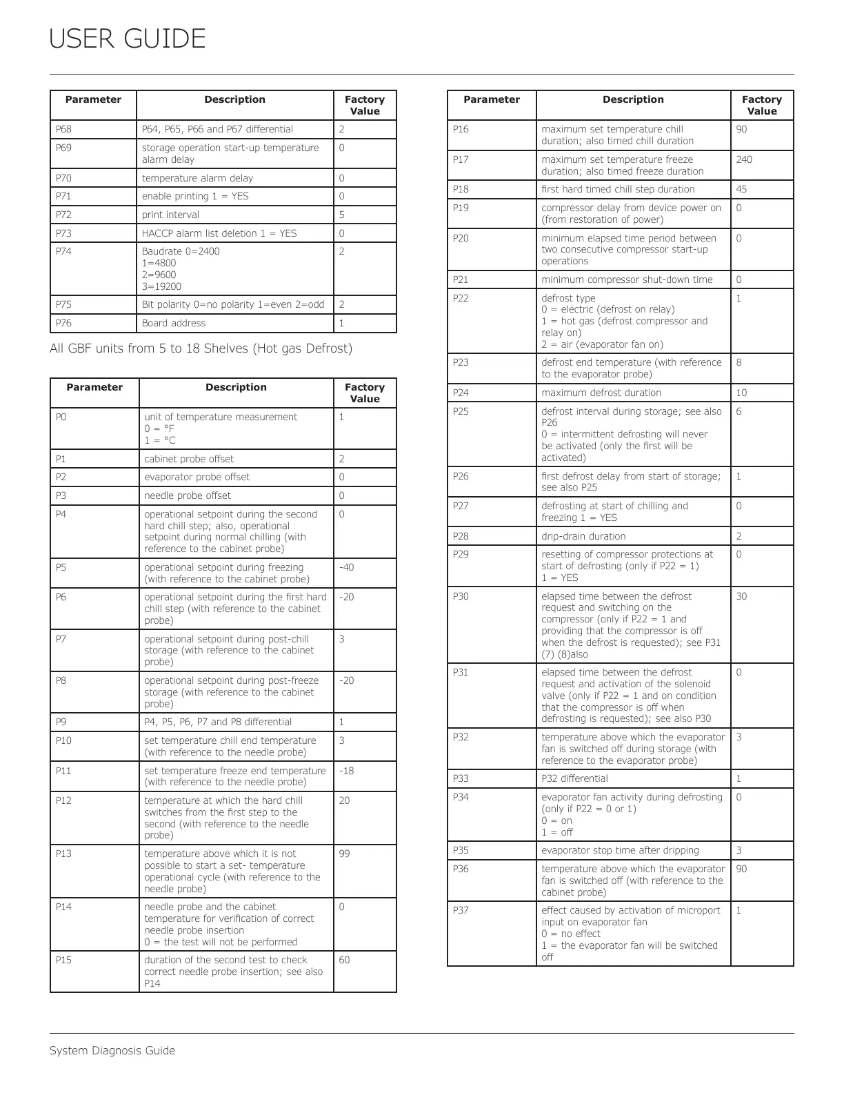
Parameter Description Factory
Value
P68 P64, P65, P66 and P67 dierential 2
P69 storage operation start-up temperature
alarm delay
0
P70 temperature alarm delay 0
P71 enable printing 1 = YES 0
P72 print interval 5
P73 HACCP alarm list deletion 1 = YES 0
P74 Baudrate 0=2400
1=4800
2=9600
3=19200
2
P75 Bit polarity 0=no polarity 1=even 2=odd 2
P76 Board address 1
All GBF units from 5 to 18 Shelves (Hot gas Defrost)
Parameter Description Factory
Value
P0 unit of temperature measurement
0 = °F
1 = °C
1
P1 cabinet probe oset 2
P2 evaporator probe oset 0
P3 needle probe oset 0
P4 operational setpoint during the second
hard chill step; also, operational
setpoint during normal chilling (with
reference to the cabinet probe)
0
P5 operational setpoint during freezing
(with reference to the cabinet probe)
-40
P6 operational setpoint during the rst hard
chill step (with reference to the cabinet
probe)
-20
P7 operational setpoint during post-chill
storage (with reference to the cabinet
probe)
3
P8 operational setpoint during post-freeze
storage (with reference to the cabinet
probe)
-20
P9 P4, P5, P6, P7 and P8 dierential 1
P10 set temperature chill end temperature
(with reference to the needle probe)
3
P11 set temperature freeze end temperature
(with reference to the needle probe)
-18
P12 temperature at which the hard chill
switches from the rst step to the
second (with reference to the needle
probe)
20
P13 temperature above which it is not
possible to start a set- temperature
operational cycle (with reference to the
needle probe)
99
P14 needle probe and the cabinet
temperature for verication of correct
needle probe insertion
0 = the test will not be performed
0
P15 duration of the second test to check
correct needle probe insertion; see also
P14
60
Parameter Description Factory
Value
P16 maximum set temperature chill
duration; also timed chill duration
90
P17 maximum set temperature freeze
duration; also timed freeze duration
240
P18 rst hard timed chill step duration 45
P19 compressor delay from device power on
(from restoration of power)
0
P20 minimum elapsed time period between
two consecutive compressor start-up
operations
0
P21 minimum compressor shut-down time 0
P22 defrost type
0 = electric (defrost on relay)
1 = hot gas (defrost compressor and
relay on)
2 = air (evaporator fan on)
1
P23 defrost end temperature (with reference
to the evaporator probe)
8
P24 maximum defrost duration 10
P25 defrost interval during storage; see also
P26
0 = intermittent defrosting will never
be activated (only the rst will be
activated)
6
P26 rst defrost delay from start of storage;
see also P25
1
P27 defrosting at start of chilling and
freezing 1 = YES
0
P28 drip-drain duration 2
P29 resetting of compressor protections at
start of defrosting (only if P22 = 1)
1 = YES
0
P30 elapsed time between the defrost
request and switching on the
compressor (only if P22 = 1 and
providing that the compressor is o
when the defrost is requested); see P31
(7) (8)also
30
P31 elapsed time between the defrost
request and activation of the solenoid
valve (only if P22 = 1 and on condition
that the compressor is o when
defrosting is requested); see also P30
0
P32 temperature above which the evaporator
fan is switched o during storage (with
reference to the evaporator probe)
3
P33 P32 dierential 1
P34 evaporator fan activity during defrosting
(only if P22 = 0 or 1)
0 = on
1 = o
0
P35 evaporator stop time after dripping 3
P36 temperature above which the evaporator
fan is switched o (with reference to the
cabinet probe)
90
P37 eect caused by activation of microport
input on evaporator fan
0 = no eect
1 = the evaporator fan will be switched
o
1
50
 Loading...