Do you have a question about the U.S. Aircore Trainer 40 and is the answer not in the manual?
Critical safety notice about the R/C kit and model, emphasizing responsibility for safe use.
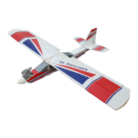
Welcome and overview of the U.S. Aircore Trainer 40's features and benefits.
Critical build and safety guidelines for assembling the model correctly.
List of materials and components needed for assembly.
List of tools necessary for building the aircraft.
Familiarize with manual, charge radio system, and understand techniques.
Unpack and identify all components by comparing them against the parts list.
Prepare parts for bending by breaking in scores, potentially using heat.
Begin assembly of the power unit by gluing plywood halves and doublers.
Complete power cartridge assembly, including nose gear block.
Construct the wing's main spar by gluing spars to dihedral braces.
Construct the fuel tank assembly using plastic tube and rubber stopper.
Finish fuel tank construction by connecting tubing and stopper.
Guidance on using contact cement for AirCore material assembly.
Build the ailerons by preparing hinge strips and attaching them to wing bottoms.
Attach ailerons to wing trailing edges, ensuring proper hinge alignment.
Prepare the leading edge for folding by exercising score lines.
Mark spar locations using pin-holes and place alignment strips.
Secure spar alignment strips to create the spar slot.
Assemble wing center ribs and install them onto the wing bottoms.
Add leading edge strips and gussets to the wing structure.
Finalize leading edge components, ensuring proper fit and glue.
Secure the main wing spar in place using contact cement.
Test wing fold alignment to ensure all parts fit correctly before gluing.
Shape and glue wing tips, then trim excess material for a clean finish.
Correct wing warpage by checking alignment and applying corrections.
Warp correction methods using delaminating and reglueing.
Fit and connect aileron control rods, ensuring proper orientation.
Apply wing wrap material to the center section of the wing.
Secure the wing wrap, ensuring a tight and neat fit.
Mount the aileron servo by cutting a hole and securing it with a servo block.
Add internal fuselage supports by gluing doublers to the inside.
Attach rail support pieces to the fuselage for structural integrity.
Secure rail doublers to the fuselage, ensuring proper alignment.
Add fuselage structural components like side boards and nose reinforcement.
Fit internal bulkheads into the fuselage structure for support.
Add front fuselage reinforcement for added strength.
Finalize nose reinforcement by gluing it securely in place.
Add the fuselage floor by placing and gluing the board into notches.
Shape the fuselage base by folding and trial fitting the bottom sections.
Complete fuselage base assembly by gluing the front and middle flaps.
Add wing support doublers to the fuselage sides for a stable mount.
Fit wing saddle bulkheads into the fuselage for proper wing alignment.
Secure wing saddle bulkheads, ensuring correct alignment with the wing saddle.
Add more wing saddle supports by installing the 6-mil doublers.
Fit fuselage windows, including windshields and side windows.
Glue fuselage windows securely in place.
Add dowels for wing attachment to the fuselage.
Prepare tail surfaces by slitting flutes for hinges on stabilizers and elevators.
Assemble tail surfaces by installing dowels and joining stabilizer halves.
Connect elevator controls by installing joiner wire and control horn.
Mount the elevator control horn securely to the elevator surface.
Finalize elevator control mounting by attaching the control horn.
Prepare tail fins and rudder by slitting hinge flutes and installing dowels.
Install rudder controls and connect the rudder to the servo.
Add the tail wheel assembly by creating and installing the tail gear wire.
Complete tail wheel installation by bending wire and securing the bracket.
Mount tail surfaces by attaching the stabilizer and fin to the fuselage.
Apply tail trim strips to the leading edges of the stabilizer and fin.
Build the main landing gear by slitting struts and assembling the components.
Finalize main landing gear by gluing struts and installing wheels.
Mount the engine onto the power cartridge, ensuring proper fit.
Attach fuel lines to the engine and carburetor.
Prepare servos by installing grommets and mounting them to the power cartridge.
Mount the remaining servos to the power cartridge.
Place the fuel tank into the power cartridge.
Secure the fuel tank in the power cartridge and attach fuel tubing.
Mount electronics by installing hook and loop material and securing receiver and battery.
Connect servos to the receiver, using extension wires and bundling them.
Bundle servo wires neatly for proper installation.
Mount the power switch on the fuselage or power cartridge.
Perform initial servo calibration by centering controls and setting arm positions.
Finalize servo adjustments by checking arm positions.
Connect the throttle control linkage, including clevis and Z-bend.
Fit the nose gear assembly through the fuselage block and attach steering.
Finalize nose gear installation and connect steering linkage to rudder servo.
Attach the main landing gear to the fuselage using rubber bands or bolts.
Adjust landing gear wheel collars for proper plane leveling.
Insert the power cartridge into the fuselage, trimming as necessary.
Secure the power cartridge with screws, ensuring clearance for components.
Mount the propeller and spinner onto the engine.
Ensure the propeller nut is tightened securely.
Achieve proper balance by adjusting the power cartridge position.
Adjust balance as needed, then remove the wing.
Connect control pushrods by attaching clevises to horns.
Finalize pushrod connections, ensuring secure clevis attachment.
Verify control surface function and directionality.
Test all control surface movements and throws for proper operation.
Mount the antenna wire through the fuselage and connect it to the tail.
Proper care for the model during storage and transportation to prevent damage.
Prevent heat damage to the model by avoiding storage in hot vehicles.
Methods for fixing damage to AirCore material and internal components.
Guidance for new pilots on finding instruction and resources.
Battery charging procedures for transmitter and receiver.
Essential propeller balancing to prevent vibration and damage.
Selecting a suitable flying location and joining local clubs.
Inspecting the assembled model for correct radio and engine installation.
Test radio control range with the engine running.
Critical safety measures for operating the model's engine.
Ground handling and steering practice.
Procedure for launching the aircraft smoothly.
Basic flight techniques and control coordination.
Safely bringing the aircraft down for a smooth touchdown.
| Brand | U.S. Aircore |
|---|---|
| Model | Trainer 40 |
| Category | Toy |
| Language | English |