40
ALTA
Installation, Operating & Service Instructions
110327-02 - 7/20
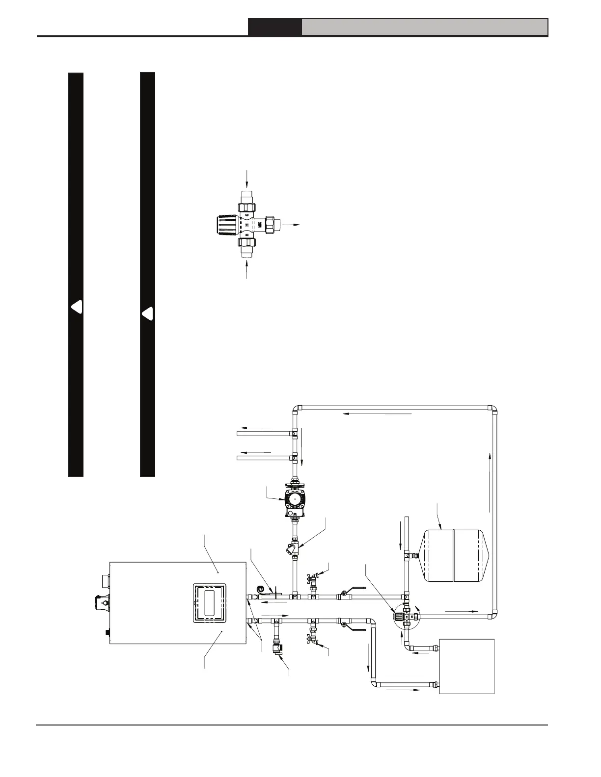
11 Domestic Water Piping (continued)
NOTICE: Heating System piping omitted for clarity.
NOTICE: Installer is responsible for piping configurations to provide proper flow rates and
meet local codes.
DANGER
Scald hazard. Under certain conditions this boiler can deliver (DHW) at temperatures
in excess of DHW setpoint in boiler control. A field supplied ASSE 1070 listed anti-
scald valve is required as part of this boiler’s installation when DHW recirculation
issued.
CAUTION
Component Damage.
Excessive heat from soldering could damage gaskets at connection between DHW
adapters and boiler. Solder connections to DHW adapters before installing gaskets.
!
!
A
DHW
Pressure
Relief Valve
Drain
Valve
Buffer Tank
(2-6 Gal.)
(optional)
Drain
Valve
ASSE 1070 Listed
Anti-Scald Valve
(required)
Cold Water Supply
Recirc. Temp. Sensor
(P/N 108703-01)
Expansion Tank
(Req'd if cold
water supply line
has check valve)
Flow Check
Valve
Recirc.
Pump
Hot Water
To Fixtures
*Supplied with boiler
DHW Strainer*
(inside boiler)
DHW Flow Limiter*
(inside boiler)
DHW Adapters*
(G 1/2" to 3/4" sweat)
Detail A
(Scale 1 : 4)
Cold Water Supply
Hot Water
(From Boiler)
Hot Water To Fixtures
Figure 11-3: DHW Piping with Recirculation
NOTICE: Additional wiring and control settings required for DHW
recirculation:
• Connect recirculation pump to "Aux Pump" terminals per Figure 13-2.
• Connect jumper, time of day clock or momentary push button to "Aux
T'Stat" terminals per Figure 13-3.
• Secure recirculation temp sensor close to boiler on cold water line.
• Connect recirculation temperature sensor to "Header sensor" terminals per
Figure 13-3.
• Turn DHW comfort mode "on". See Section 16 Operation and Table 16-11.
 Loading...