ULTRA POWER TWIN II-30 P/N 39-941705
ULTRA POWER TWIN II-22 P/N 39-941707
REV12/2013
APPLICATION
TheprimarypurposeofyourPowerTwinIIistoprovide
rock solid stabilization for maximum comfort while
using your RV in a parked position.To obtain this
desired end result and eliminate the possibility of
damage to your RV or the Power Twin II, it is very
importanttofollow
thesestep‐by‐stepinstructions.
IMPORTANT:DO NOT OPERATE THE POWER TWIN II
BEFOREREADINGTHEOPERATINGINSTRUCTIONS.
The Power Twin II will assist you in final lifting and
leveling,basedonthePowerTwinIIPowerCurveGraph
which shows pounds of lift in relation to the ground
clearance
fromthebottomoftheframe.
BymeasuringthegroundclearanceonyourRVyoucan
determine the maximum amount of lift your Power
TwinIIwillprovideforfinalleveling.
NOTE:THE POUNDS OF LIFT INCREASES AS THE
DISTANCE,FROMGROUNDTOFRAME,INCREASES.
SAFETYANDDAMAGEWARNING
CAUTION:ALWAYSFOLLOWTHESE
INSTALLATIONANDOPERATING
INSTRUCTIONSTOPREVENTDAMAGETO
YOURRVANDTOPREVENTPERSONAL
INJURY.
INSTALLATION
The Power Twin II‐30 does not come assembled.
Pleasefollowallofthestepsof theseinstructions.The
Power Twin II‐22 is pre‐assembled, so please skip to
Step3.
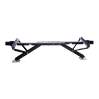
❶ Attachmountingplate(#2)tomainassembly
channel(#1)usingfour(4)M8‐1.25x25mmcarriage
bolts (#14) and
four (4) M8x1.25 NYLOCK nuts
(#15). Make sure the mounting plateissquareto
the main channel assembly before tightening the
nuts.
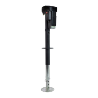
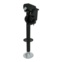
❷ Attachthetwo(2)armsupportbraces(#13)
to the mounting plate (#2) using two (2)
M12‐1.75x30mmhexheadbolts(#16)andtwo(2)
M12x1.75NYLOCKnuts
(#17).
Place the plastic washer (#11) between the arm
andthemountingbracket.A ttachtheotherend
ofthearmsupportbr acestothelegassembly(#8)
usingone(1)M12‐1.75x100mmhexheadbolt(#18)
andone(1)M12x1.75NYLOCKnut(#17)byplacing
the leg spacer (#10) inside the
leg assembly and
pushing theboltthroughtheone sideofthe leg,
throughthespacerandout oftheothersideofthe
legchannel.
Besuretoplacetheplasticwasher(#11)between
thearmandthelegbracebeforepushingthebolt
throughthehole.
Tightenall
boltsandnutsuntilsnug.Donotover
tightenasthesearepivotpoints.
REPEATsteps1and2forthesecondlegassembly
(39‐841700PTII‐30).
INSTALLATION/OPERATION