Do you have a question about the Ultrasonix SONIX Series and is the answer not in the manual?
User manual reference for operators familiar with ultrasound imaging techniques.
Explains formatting and symbols used throughout the manual for clarity.
Information regarding availability of updated user manuals for system updates.
Details hardware options specific to the CEP platform running OP software.
Cautionary notice regarding system voltage settings and user responsibilities.
Warning about using networking options within organizational firewalls.
Recommendations for protecting patient data and system hard drive contents.
Outlines the terms and conditions of the software license agreement.
Lists trademarks and patents associated with the SONIX systems.
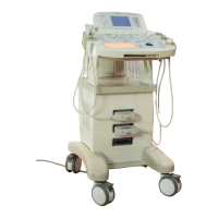
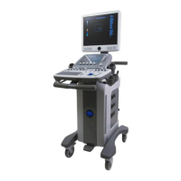
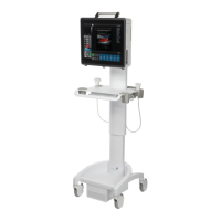
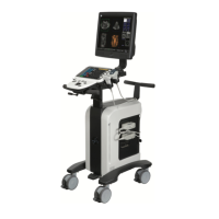
Overview of the major physical parts of the SONIX ultrasound system.
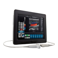
Description of the controls and layout of the operator console.
Details about the system case, including PC and connectivity panel.
Location and function of the back connectivity panel.
Description of the power panel components on the system case.
Information on the Uninterruptible Power Supply (UPS) for CEP models.
Details on the optional barcode reader for data entry.
Information on power cord types and lengths for different platforms.
Description of the wireless adapter option for network connectivity.
Details about the transducer basket included with the CEP system.
Description of the cable hooks on the operator console for cable management.
Information about the console cover for system protection.
Step-by-step guide on how to turn on the SONIX ultrasound system.
Instructions for connecting and disconnecting transducers to the system.
Overview of the QSONIX button's functions: Quick Exam Start-Up, Tutorial, and Support.
Guide to entering patient and exam-related data into the system.
Instructions for selecting and changing the connected transducer.
Guide to choosing the appropriate application and imaging preset.
Steps to start an exam for a new patient using manual entry or barcode reader.
Procedure for properly ending the current patient exam session.
Explanation of the Local, Worklist, and Hide storage/database tabs.
Instructions on creating and saving user-defined imaging presets.
Details on 2D and M-Mode imaging parameters and controls.
Explanation of controls for 2D imaging, including frequencies and parameters.
Description of Clarity mode for adaptive filtering and speckle reduction.
Instructions for activating and exiting Real Time Spatial Compound Imaging.
Guide to activating and exiting the 2D zoom feature for magnification.
Instructions for activating and using the dual imaging format.
Instructions for activating and using the quad imaging format.
Details on M-Mode imaging parameters and controls.
Instructions for storing and reviewing CINE clips.
Overview of Color and Power Doppler imaging for blood flow detection.
Guide to activating and adjusting Color Doppler imaging parameters.
Instructions for activating and adjusting Color Power Doppler imaging.
Procedure to activate split screen with live 2D/Color and live 2D.
Details on Pulsed Wave Doppler and Triplex imaging modes.
Instructions for activating and adjusting PW Doppler imaging.
Explanation of Triplex mode combining 2D/Color and PW Doppler.
Description of Elastography for measuring tissue stiffness.
Guide to generating panoramic views of the ultrasound image field.
Overview of 3D/4D image optimization parameters.
Instructions for acquiring Freehand 3D images with non-4D transducers.
Procedure for obtaining a 3D image using a SONIX 4D transducer.
Procedure for obtaining a 4D image using a SONIX 4D transducer.
Details on the additional line across the bottom of the LCD for 4D images.
Explanation of the four image formats available for 3D/4D display.
Guide to optimizing a 3D image after acquisition.
Instructions for optimizing a 4D image during or after acquisition.
Procedure to set VR or MPR Rendering to rotate 3D/4D images.
Information on accessing CINE options after acquiring a 4D image.
Instructions on designing and saving user-defined 3D/4D presets.
Initial touch screen presentation for Advanced 3D/4D Imaging.
Overview of available touch screen controls for Advanced 3D/4D Imaging.
Switch between image formats and basic imaging parameters in 4D Main.
Details on touch screen controls for editing image contents in 4D Advanced.
Explanation of settings for VR image display: Map, Contrast, Background.
Description of CINE controls identical to regular 2D imaging.
Overview of measurement options available in MEASURE MODE for 4D.
Description of five separate onscreen menus/modes on the LCD display.
Enables changing image presentation format and active plane (A, B, C).
Allows performing measurements on frozen or recalled images.
Enables selection of detailed views of individual slices (A, B, C plane).
Allows configuration of image style, surface settings, and direction.
Enables users to manage system presets and user-defined settings.
Details on the additional line at the bottom of the LCD for 3D/4D images.
Guide to acquiring 3D and 4D images and subsequent optimization.
Procedure for acquiring a 3D image with a SONIX 4D transducer.
Procedure for acquiring a 4D image with a SONIX 4D transducer.
Instructions for optimizing and editing saved 3D or 4D images.
Information on accessing CINE options after 4D image acquisition.
Overview of default and user-defined presets for Advanced 3D/4D Imaging.
Procedure to reset User 1 and User 2 presets to factory defaults.
How to select a default preset applied automatically after acquisition.
Guide to creating and saving user-defined presets for 3D/4D imaging.
Instructions on loading edited parameters of USER 1-5 after acquisition.
Overview of accessing 2D basic measurements via the touch screen.
Procedure to perform a 2D linear measurement using calipers.
Methods for performing Area or Circumference measurements: Ellipse and Trace.
Step-by-step guide to performing a volume calculation.
Procedure to perform a % Diameter Reduction calculation.
Methods for performing % Area Reduction: Ellipse and Trace.
Basic measurements available in M-Mode imaging.
Procedure to perform an M-Mode heart rate measurement.
Procedure to perform M-Mode slope measurements.
Basic measurements available in Pulsed Wave Doppler.
Procedure to perform velocity measurements in PW Doppler.
Instructions for manual trace measurements in Doppler.
Procedure to perform an auto trace measurement using D-Range.
Procedure to perform a Doppler heart rate measurement.
Details on application-specific measurements and calculations.
Information on accessing and viewing clinical analysis reports.
General information about reports and how to access them.
Specific features and functionalities of Obstetrical reports.
Enables users to label images with text and annotations.
Instructions for entering text using the system keyboard.
Procedure to set or reset the text/annotation cursor's home position.
Guide to entering application-specific annotations.
Instructions for deleting text and annotations from an image.
How to enter and manage text arrows on the image.
Enables users to label images with predefined pictograms.
Customization options for user-specific system settings.
Setup for managing factory default and user-defined imaging presets.
Ability to modify specific annotations attached to presets.
Ability to attach/detach and reorder pictograms for presets.
Setup for attaching/detaching 3D/4D presets to user-defined and default presets.
Configuration of three global annotation settings.
Customization of onscreen appearance for calipers and measurement displays.
Selection of display options for measurement values onscreen.
Configuration of authors for Obstetrical calculations.
Procedure for creating new Obstetrical calculation authors and lookup tables.
Configuration of 3D Config parameters and management of user-defined presets.
Adjustment of various display parameters for the LCD and touch screen.
Enables selection of DICOM servers for Storage and Print.
Setting the onscreen Biopsy Guide Orientation to Diagonal or Central.
Configuration for viewing live imaging remotely via Streaming Video.
Instructions for downloading and setting up VLC Media Player for SONIX Live.
Instructions for configuring SONIX Live streaming with Windows Media Player.
Configuration options for high-level system parameters and maintenance.
Configuration of Institution Name, Regional, Imaging Modes, and other system settings.
Dialog for configuring the system's network connection.
Steps to configure an Ethernet (LAN) connection for the system.
Steps to configure a Dial-up Network connection for the system.
Guide to configuring wireless network connection options.
Instructions for adding extra online chat support IP addresses.
Procedure for configuring online remote support with Ultrasonix Technical Support.
Enables configuration of DICOM Storage, Print, and Worklist.
Settings for configuring DICOM image storage.
Settings for configuring DICOM Print functionality.
Settings for configuring the DICOM Worklist SCU.
Configuration of the three console PRINT buttons for defined actions.
Software configuration for approved system peripherals.
Dialog to configure a laser or inkjet paper printer connected to the system.
Procedure to adjust LCD display settings like saturation, hue, and gamma.
Dialog to enable/disable live output video (Video Out).
Configuration of the desired operation for the footswitch.
Dialog to change Brightness/Contrast of images transferred to peripherals.
Configuration options for Exam Management page and patient data display.
Enables display of relevant icons at the bottom right of the LCD display.
Selection of storage between Image and Full Screen, and loop time configuration.
Option to install software updates via Internet, CD/DVD, or USB key.
Displays available system options, status, and expiry dates.
Details on how patient files, images, and CINE clips are stored.
Accessing and reviewing stored patient images and exam files.
Procedure for deleting individual images or complete exams.
Enables transfer of stored images and CINE clips to storage media.
Overview of the system case connectivity panel and its ports.
Description of the back connectivity panel connectors.
Details on the USB ports and DVD/CD writer on the operator console.
Instructions for connecting the software dongle for Advanced 3D/4D Imaging.
List of peripherals approved for use with the SONIX system.
Information regarding the Uninterruptible Power Supply (UPS) for CEP models.
Circumstances under which the UPS battery enters sleep mode and how to wake it.
Procedure for activating an emergency shutdown using the EPO switch.
Instructions for connecting the standard barcode reader.
Details for connecting the barcode reader to the CEP console.
Details for connecting the barcode reader to OP/SP/RP systems.
Information on power cord unwinding and retracting.
Details on installing and configuring the wireless adapter.
Instructions for installing the console cover.
Important information regarding the safe use of the SONIX ultrasound system.
Explanation of the ALARA principle and acoustic power output displays.
General safety precautions for operating the SONIX ultrasound system.
Specific safety warnings and precautions for the UPS unit.
Definitions and meanings of system symbols and labels.
Electrical safety standards and requirements for SONIX systems.
Electrical safety classification and compliance for SONIX models.
Electrical safety requirements specific to the SONIX CEP system.
Electrical safety information for barcode readers and other hardware.
Precautions regarding Electro-Magnetic Compatibility (EMC).
Recommended operating and storage environmental conditions.
Information on transducer surface temperature limits and heating prevention.
Caution regarding the use of transducer covers containing latex.
Overview of system specifications including clinical applications and imaging modes.
Guidelines for handling and inspecting SONIX transducers.
General guidelines recommended by Ultrasonix for transducer use.
List of recommended ultrasound coupling gels for SONIX transducers.
Recommendations and warnings for cleaning non-invasive transducers.
Recommendations and warnings for cleaning invasive transducers.
Customer responsibilities for disinfecting and packaging transducers for shipment.
Cleaning instructions for various system components.
Precautions and instructions for cleaning the LCD display and cabinet.
Precautions and instructions for cleaning the operator console touch screen.
Precautions and instructions for cleaning the operator console.
Precautions and instructions for cleaning the console cover.
Cleaning instructions for the barcode reader.
Cleaning instructions for power cords.
Cleaning instructions for the wireless adapter.
Instructions for cleaning the transducer basket.
Table listing specifications for various SONIX transducers.
Table of transducers used for Advanced 3D/4D measurement accuracy tests.
Acoustic output reporting tables for all transducers and modes.
Tables indicating diagnostic ultrasound use for various clinical applications.
List of references for Obstetric (OB) related measurements and analysis.
References for gestational age calculations based on fetal measurements.
References for fetal growth analysis based on various measurements.
List of references for general and cardiac ultrasound measurements.
| Display Type | LCD |
|---|---|
| Power Requirements | 100-240V AC, 50/60 Hz |
| Imaging Modes | B-mode, M-mode, Color Doppler, Power Doppler, Pulsed Wave Doppler, Continuous Wave Doppler |
| Connectivity | USB, Ethernet, DICOM |
| Ports | USB, Ethernet |