Lit: when the filament is ON and the emission current is
normal.
Blink: When the filament is ON and the emission current
is abnormal.
Lit when degassing is ON.
Lit when in the program setting mode.
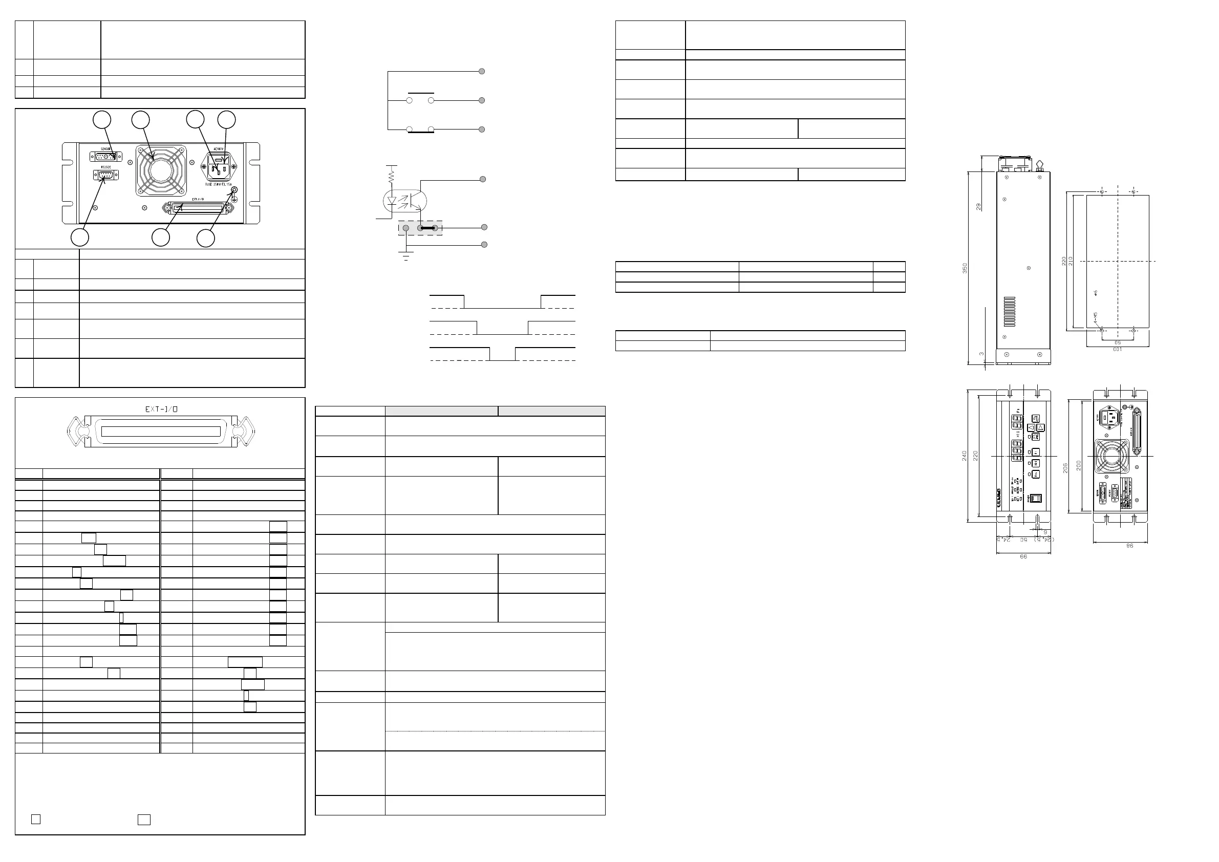
Connector for connecting the sensor head cable.
(multi-core/coaxial compound cable)
I/O connector for data and signals
Connector for communication (D-sub 9-pin pin connector)
Fan for radiating (blowing out) the heat in the gauge.
Connector for connecting 3-core power cord with grounding
terminal.
Fuse (2-ampere rapid action type) for protecting the gauge from
over-current.
Ground terminal for this gauge. Attach M4 solder less terminal
before use. Analog ground, digital ground and frame ground
are common.
EMISSION
※1)
Em-Hi / Em-Lo
• A, B, C and D in PRESSURE DATA A-b0 and later correspond to «A. B 10
DC» of the indicator. Refer to 10. EXTERNAL INNPUT/OUTPUT for
more information.
• Digital output common is pin 5 by standard setting.
• The digital input power is the internal power by standard setting.
• Digital input common is 23, 24, 48, and 49.
•
of signal identification (e.g. ON) indicates the LOW status (short, negative
logic).
※1) Em-Hi: 1mA(GI-M2), Em-Lo:10μA(GI-M2)
2.1. Set Point Output
AC: 125V
MAX
, 0.5A
MAX
DC: 24V
MAX
,1.0A
MAX
2.2. External Digital Output
24V
MAX
,50mA
MAX
,saturation voltage 1V
2.3.Method of External Control
3.Specifications and Components
3.1.Standard Specifications
Mantissa part 3 digits, exponent part 2 digits digital display
□.□□
10□□
※1)
M-11,M-12,M-13,M-14,
M-15
WIT-G type, WIB-G type,
WIB-N3
Measurement
pressure range
5.00×10
-8
~
9.99×10
0
(Pa)
WIT : 1.30×10
-5
-
6.70×10
-1
(Pa)
WIB : 1.30×10
-6
-
1.30×10
-2
(Pa)
Grid potential: 150(V), Filament potential: 25(V), Collector
potential:0(V)
WIT: 0.139 Pa
-1
WIB: 0.083 Pa
-1
Pressure
protecting
function
WIT: 9.99×10
-1
Pa
WIB: 2.00×10
-1
Pa
Direct electrical heating of grid AC Power 1.5VA
Normal mode : Operates according to DEGAS ON/OFF signal.
Auto OFF mode : When this mode is set, degassing is
automatically turned off after a preset time by setting an
arbitrary time of 01 to 99 minutes
Settiong of range hold
、
Selection of filament
、
Setting of
sensitivity
Each digit mantissa part linear output,
All measurement ranges pseudo-log. Output,
Designated range hold linear output, LOG Output
Resolution : 10mV
Output impedance : Approx. 100 ohms
Two points can be set independently.
Relay contact output (COM, a contact, b contact for each
setting).
Contact capacity AC:125V
MAX
,0.5A
MAX
/ DC: 24V
MAX
,1.0A
MAX
Control changeover, Filament ON/OFF, Filament 2/1, Degas
ON/OFF, Range hold, External protecting
Analog output (0-10V), BDC output, Power condition,
Filament ON/OFF, Emission setting, Degas ON/OFF, Emission
valid OK/NG
Operating
temperature range
15 ~ 80 % (No condensation)
BS.SEMKO EWM 3.15A (Fuji Terminal Industry) (2 pc)
※1) Pressure display can set that mantissa part 2 digits, exponent part 2 digits
digital display (□.□□ 10□□).
※2) 10 A and 1.0 mA are automatically changed over depending on pressure,1.0
mA is available when the pressure measurement value is 0.79 10
-2
Pa or less
※3) When use a tungsten filament, it is necessary to do pressure protection of a set
point of functioning in 9.9×10
-3
Pa
3.2. Standard Accessories
External input/output connector
57-30500: DDK or equivalent
125 V, 10 A, 3-pin cable, 3 m long
This gauge does not come with the RS-232C communication cable. Use a
commercially available RS-232C cable (cross type).
3.3. Options
4.Warranty
This product was shipped after rigid company inspection. However, in case any
failure occurs under ULVAC’s responsibility, such as defect in manufacturing and
damage during transportation, Buyer shall inform ULVAC, Inc. or the local
ULVAC representatives. ULVAC will repair or exchange it at free of charge.
Warrantable Items: This unit
Duration of guarantee: One (1) year after shipping date from ULVAC
Warrantee scope
1) Domestic business in Japan: Product, which has damage, caused by a failure
on delivery.
2) Direct export transaction: Product, which has damage, caused by a failure on
delivery. The warrantee scope shall confirm to the new INCOTERMS.
3) Products not satisfying meet the standard specifications although the product
is used under the normal service conditions such as temperature range and
power etc.
Response procedure
1) Domestic business in Japan: ULVAC send a replacement or Buyer return the
defective items to ULVAC, Inc. or to the local ULVAC representatives for
repair. If field service is required, Buyer shall ask ULVAC, Inc. or the local
ULVAC representatives.
2) Direct export transaction: ULVAC send a replacement or Buyer return the
defective items to ULVAC, Inc. or to the local ULVAC representatives for
repair. Return charge shall be paid by Buyer.
Disclaimer
1) Failure occurred after expiration of warranty period
2) Failure caused by force majeure, such as fire, storm and flood damage,
earthquake, lightning strike, war etc
3) Failure occurred due to carelessness handling or faulty usage
4) Products remodeled, disassembled or repaired without ULVAC’s acceptance
5) Failure occurred under abnormal environment, such as intense
electromagnetic field, radiation, high-temperature, high-humidity, flammable
gases, corrosive gases, dust etc.
6) Failure occurred by noise
7) Product deficiency or secondary damnification occurred to Buyer, from law
suit to ULVAC by third party for patent infringement.
8) Sensor head being used (expiration of life, measurement error, etc.)
9) Sensor head cable being used (cable burnout due to improper installation,
poor contact, etc.)
Others
1) In case, special agreement or memorandum for specifications is made
individually, the descriptions are prior to this article “13 Product Warranty”.
2) Buyer shall inform ULVAC when this product is exported out of Japan. In
the meantime, Buyer shall take necessary procedures according to Foreign
Exchange and Foreign Trade Law.
3) As for the question and consultation, Buyer shall check the model and serial
number and ask the local representative or ULVAC, Inc.
4) The content of this document is subject to change without notice in future.
5. Certificate of Contamination
Please enter the operating condition/trouble symptom of your vacuum gauge in
this form and submit it to your local ULVAC service station or sales office after
signing it. The form is available for download from ULVAC website.
6. Networks
ULVAC, Inc. http://www.ulvac.co.jp/eng/
Service Centers http://www.ulvac.co.jp/eng/support/service/index.html
Sales Office http://www.ulvac.co.jp/eng/support/sales_office/index.html
7. Related Drawings
ULVAC, Inc.
Components Division,
http://www.ulvac.co.jp/
a接点
2(27)
COM
SET1
(SET2)
1(26)
3(28)
b接点
”HP4"
External digital
output (BCD etc.)
5:EXT-OUT COM
23,48:D-GND
(24,49:A-GND)
GND
ISO
REMOTE
FIL-ON
DEGAS-ON
LOCAL
FIL-OFF
DEGAS-OFF
Hi
Lo
Hi
Lo
Hi
Lo
REMOTE/LOCAL
FIL ON/OFF
DEGAS ON/OFF
(Front panel)
(Side panel)
(Panel cut)
(Rack-mount)
(Fan)
or
(Rear panel)
(Max dimension)
(Main body)
(Main body
)
 Loading...