1 2
3
4
5
6
7
8
9 10
11 12
13
14
15 16
17
18
19 20
P/N:110401109689X
Preface
Thank you for purchasing this brand new product. In order to use this product
safely and correctly, please read this manual thoroughly, especially the safety
notes.
After reading this manual, it is recommended to keep the manual at an easily
accessible place, preferably close to the device, for future reference.
Limited Warranty and Liability
Uni-Trend guarantees that the product is free from any defect in material and
workmanship within one year from the purchase date. This warranty does
not apply to damage caused by accident, negligence, misuse, modification,
contamination or mishandling. The dealer shall not be entitled to give any
other warranty on behalf of Uni-Trend. If you need warranty service within
the warranty period, please contact your seller directly.
Uni-Trend will not be responsible for any special, indirect, incidental or
subsequent damage or loss caused by using this device.
I. Safety Information
This manual includes precautions and safety regulations for safe use of the
device. Please read and understand the content carefully before use.
1. Do not use or store this device in dusty, hot or wet environments.
2. Both the transmitter and receiver of this device are charged with a DC 5V
power adapter, and the charging time is about 2 hours.
3. Do not use this device on live circuits exceeding AC 60V or DC 70V.
4. Do not use this device during thunderstorms.
The meaning of the symbol associated with this device:
Complies with European Union standards
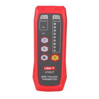
II. Structure
The UT683KIT is an intelligent wire tracker for noiseless wire tracking. The
RJ45 jack of the transmitter can enable tracking and flashing functions
simultaneously to help you quickly and accurately locate the target cable.
The RJ11 jack can automatically identify open circuit, short circuit, polarity,
ringing signal, and other states to help you quickly distinguish cable faults.
It is an ideal tool for integrated wiring and installation and maintenance of
weak electricity systems.
RJ 11 jack
POLARITY indicator
CONT indicator
Switch button
Tracking button
Antenna
Charging state indicator
NCV button
Tracking button
Line sequence indicators
RJ 45 jack
PORT FLASH light
Line sequence indicators
Power button
Validating indicator
NCV indicator
Sensitivity knob
Flashlight button
Power button
RJ45 jack
IV. Network Line Tracking
1. Insert the RJ45 plug of the network line into the RJ45 jack of the transmitter.
2. Press the button on the transmitter to enable the tracking function. In
tracking mode, press the button to enable the flashing function
simultaneously. If the target network line is connected to an active switch,
router or network card, the PORT FLASH light of the transmitter will flash
synchronously with the network port indicator.
3. Press the button on the receiver to start tracking. When beeps are heard,
the target network line is found.
V. Telephone Line Tracking
1. Insert the RJ11 plug of the telephone line into the RJ11 jack of the transmitter.
2. Press the button on the transmitter to enable the tracking function.
4. Press the button on the receiver to start tracking. When beeps are heard,
the target telephone line is found.
VI. Power Cable Tracking
1. Use the RJ11 alligator clip adapter cable to connect the transmitter and
metal cable being tracked.
2. Press the button on the transmitter to enable the tracking function.
3. Press the button on the receiver to start tracking. When beeps are heard,
the target cable is found.
VII. Demonstration of Tracking Operation
UT683KIT
Wire Tracker User Manual
III. Packing List
Item
Qty
Item
Qty
Transmitter
1
Receiver
1
Micro USB charging cable
1
RJ11 adapter cable
1
RJ11 alligator clip adapter cable
1
RJ45 adapter cable
1
User manual
1
Pouch
1
Wall socket
(RJ11/RJ45 socket)
Test indicators
Locating cables
Isolating cables
Volume control