6
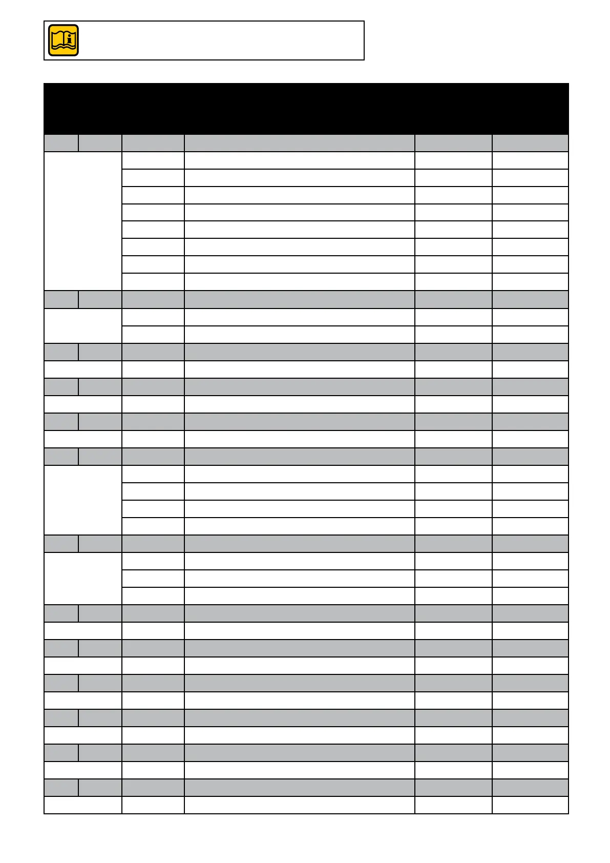
Code
Sym-
bol
Value Description Default
settings
BCM user
settings
803 Srv Enabled services
16 All services disabled 16
17 Heating only
18
Antifreeze only
19 Heating + Antifreeze 19
24 DHW only
25 Heating + DHW
26 DHW + Antifreeze
27 Heating + DHW + Antifreeze
483 rP °K
0 Disabled
1 ÷ 500 Maximum Δ temperature (° C x 10) 0 0
34 HY °K Burner Hysteresis
50 ÷ 200 (°C x 10) 5 =
31 HL °C CH#1: Burner Minimum Set-point
200 ÷ 400 250 =
39 HH °C CH#2: Burner Maximum Set-point
450 ÷ 850 850 =
799 AC Analogue input function 0/10 V:
0 Manual adjustment target temperature
1 External temperature sensor 1
2 0 / 10 V Target temperature control
3 0 / 10 V Modulation control
376 DI1 Programmable Input #1
0 Enabling CH Heating Service 0
1 Enabling heat generator
2 Reset alarms
322 Po min Pump: Post-circulation
1 ÷ 10 5
341 PL V Minimum output pump modulation
0 ÷ 100 burner level V x 10 30
313 Pr V Maximum output pump modulation
0 ÷ 100 burner level V x 10 100
792 CHP % Heating: Maximum modulation
0 ÷ 100 100
611 POT °K Gen: Err. Max. Parallel
0/1 ÷ 30 5
612 POL % Gen: Mod. Max. Parallel
0 ÷ 100 0
3.1 - BCM (HCM) parameters - General settings / user settings
to edit BCM parameters
(see chap. 2.8 - USER INTERFACE devices menu)
 Loading...