28
Adjustment info
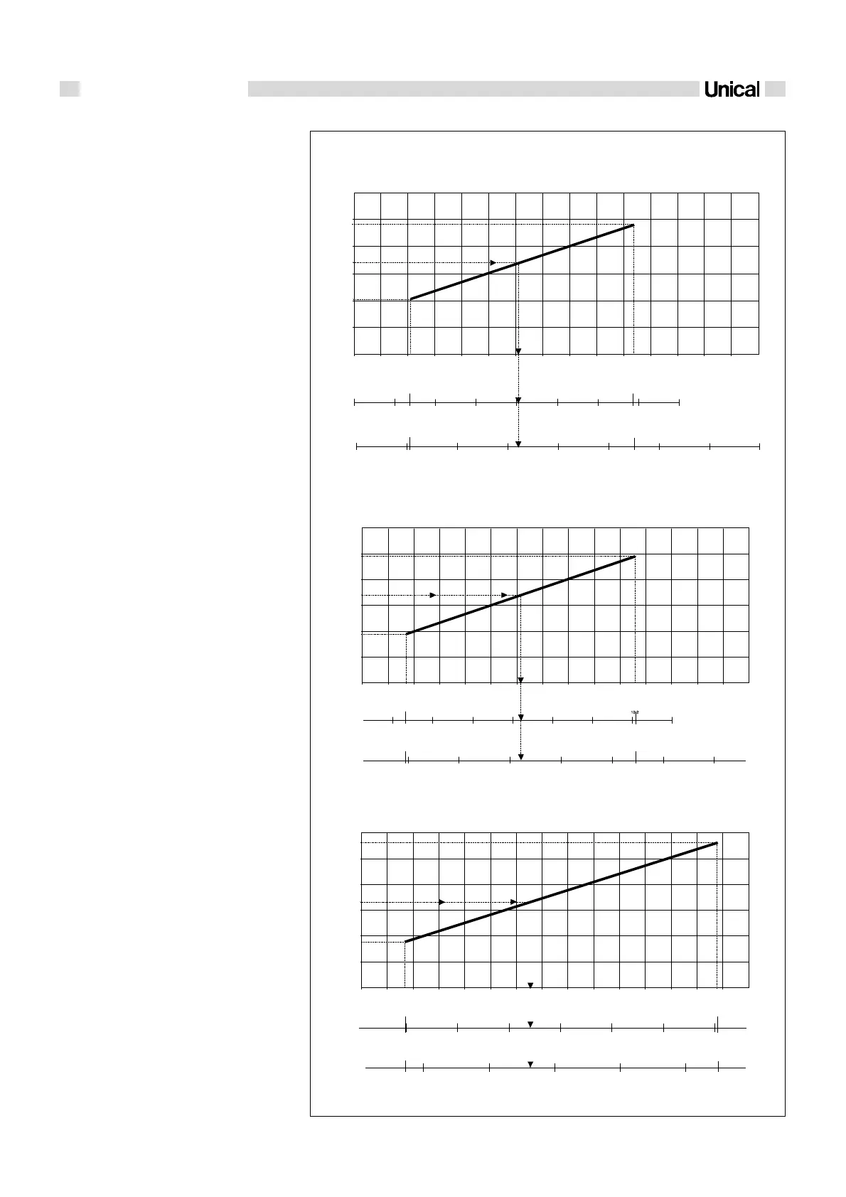
fig. 34
IVEN 04 CTN 24 F - IVEN 04 RTN 24 (A)
IVEN 04 CTFS 24 F - IVEN 04 RTFS 24 (B)
IVEN 04 CTFS 28 F - IVEN 04 RTFS 28 (C)
5
10
0 1 2 3 4 5 6 7 8 9 11 12 13 14 15
0
10
15
20
25
5,3
27,6
5
10
15 20 25 30
0
35 40
6,9
34,2
Natural gas G20 - 20 mbar
0 1 2 3 4 5 6 7 8 9 11 12 13 14 15
0
10
15
20
25
Natural gas G20 - 20 mbar
24,5
9,95
1,7 10,6
0 5
10 15
20
25
4,8
27,3
5
10
15
20 25 30 35
40
0
Natural G20 - 20 mbar
2.8 ADJUSTEMENT OF
THE OUTPUT TO
THE C.H. SYSTEM'S
NEEDS
Connect the pressure gauge to the burner as
previously shown in fig. 30, switch on the boi-
ler in heating mode and proceed as follows:
- Wait about 50 sec. to allow the burner pres-
sure to reach the standard operating va-
lue.
- Check the pressure value and through the
diagrams of fig. 34 estimate if the boiler
output is correct for heating needs.
- If not, act on the adjuster ''1 CH-POWER''
(fig. 31) on the panel board and turn it to
reach the desired value (clockwise to in-
crease, or anticlockwise to reduce the
pressure).
- Then establish the pressure value corre-
sponding to the required output.
Example:
Assuming that the heating system which is
using a IVEN CTN 24 F boiler has a total ab-
sorption of 17 kW. Using the graph ‘’A’’ in fi-
gure 34 it is possible to determine the burner
pressure, which will be:
- 6,18 mbar if the boiler runs on natural gas
- 20,5 mbar if the boiler runs on propan gas.
- 16,3 mbar if the boiler runs on butan gas.
Acting on potentiometer 1 - CH POWER set
the pressure resulting from the diagram.
GAS PRESSURE BURNER DIAGRAM CORRESPONDING TO
THE SYSTEMS OUTPUT

 Loading...